


7
ULTRAMATCH PRO SRC2496
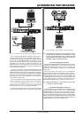
2. CONTROL ELEMENTS
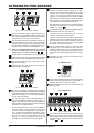
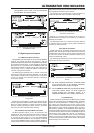
The LEDs 32 kHz, 44.1 kHz, 48 kHz, 88.2 kHz and 96 kHz
read the sampling rate selected with the SAMPLE RATE
switch. If the sampling rate is preset by an external
wordclock or generated via the digital input signal, the LEDs
light up constantly, thus reading the external sampling rate
(with a deviation of ± 2 kHz). The next value (= deviation of
>2 kHz) is displayed by one of the LEDs flashing.
The CLOCK switch allows you to select the source
determining the sampling rate at the digital output of your
ULTRAMATCH PRO.
The PLL LOCK LED shows you that your SRC2496 is
processing properly the wordclock signals applied.
The INTERNAL LED lights up when the SRC2496 generates
the sampling rate by itself (master), which is the preferred
mode for the ULTRAMATCH PRO acting as an A/D converter.
The EXTERNAL LED lights up when the sampling rate is
governed by an external wordclock signal. The external
mode also allows you to generate sampling rates at the
output that could not be generated by the SRC2496 as a
master unit.
When the DIG IN LED lights up, your SRC2496 uses the
wordclock signal included in the digital audio signal fed into
the unit. This setting is useful if you do not want to convert
the sampling rate, but only the format of the digital output
signal (S/PDIF to AES/EBU or vice versa).
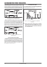
The FORMAT switch determines the format of the digital
data stream on the output side, as defined in the Channel
Status data. Available formats are AES/EBU and S/PDIF.
The LEDs AES/EBU and S/PDIF show the adjusted output
format, which is present at all three digital outputs. Using
an appropriate cable (see chapter 5.3.5) you could also
route an S/PDIF signal from the XLR output to a second
unit, in case the RCA output is already in use.
Use the WORDLENGTH switch to select the digital word
length of your choice (16, 20 or 24 bits).
+ If you want to set the digital word length to a lower
value (e.g. to record 24-bit signals with 16 bits on
CD, MD or DAT), we recommend that you switch on
the dither function, so as to limit the distortion
resulting from the omission of the additional bits
to an inaudible minimum.
The LEDs 24 BIT, 20 BIT and 16 BIT read the word length
selected.
The DITHER switch enables/disables the dither function.
The corresponding LED lights up when this function is active.
Heres a concise explanation of the dither function: Whenever
analog signals are converted to digital (numerical values!),
the finite number of digits available for the mathematical
description of the analog signals (electrical voltages that are
constant in the time and value domains) inevitably result in
rounding errors and misinterpretations of the analog signals
(quantization errors). In particular, signals with a very small
amplitude are affected by an audible system error known as
granular noise. Such errors can be suppressed by adding
white noise. This type of noise has an exactly defined
amplitude (minimum amplitude that can be detected only by
measuring instruments and by no means affects the audio
signal) and broadband frequency distribution, and is called
dither signal. Combine this with the high internal resolution of
24 bits, and you can generate an audio signal of excellent
quality.
Reducing the digital word length (e.g. from 24 bits to
20 bits) also means a reduction of the resolution. The
resulting misinterpretations, which are more likely to result
by this word length reduction can be purposefully
suppressed with the dither function.
The EMPH LED lights up when the emphasis bit has been
set in the output signal. Use the EMPHASIS switch to enable/
disable this function. To avoid sound deterioration, the LED
in the output section should read the same status as the
EMPH LED in the input section. In the rare case of a signal
containing an emphasis bit without any treble boost applied,
you can correct this here and switch off the emphasis bit
(detailed information can be found in chapter 3.4).
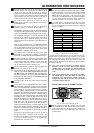
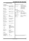
The COPY switch (= copyright) allows you to set the status
of the copy bits in the transmitted data stream. The LEDs
COPY and ORIG inform you about the current status of
the copy protection:
COPY-LED on
ORIG-LED on
COPY-LED on
ORIG-LED off
COPY-LED off
ORIG-LED off
COPY-LED off
ORIG-LED on
digital recording only once
digital recording not possible
digital recording unlimited
Tab. 2.1: Overview of copy bit settings
If both COPY and ORIG light up, you can make one copy only.
Subsequently, the data will be copy protected. If only COPY
lights up, digital copies cannot be made. If both LEDs are out, you
can make digital recordings without any limitations. Press the
switch to change the status of the determining bits and allow for
unrestricted copying.
+ This option applies exclusively to S/PDIF signals,
because the Serial Copy Management System
(SCMS) exists in this format only. Signals based on
the professional AES/EBU format can be copied
freely.
+ Even though removing the copyright bit is possible,
we would like to alert you about the fact that
copyright and duplication rights must be
safeguarded. We did not produce this equipment
to facilitate illegal copying!
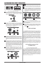
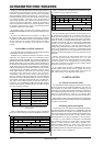
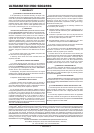
2.2 Rear panel of the ULTRAMATCH PRO
Fig. 2.6: Mains connector/fuse holder
MAINS CONNECTOR/FUSE HOLDER. Use the power
cord supplied with the SRC2496 to connect the unit to the
mains. Please note the instructions given in chapter 1.2.
Blown fuses should only be replaced by fuses of the same
type and rating.