


— 5 —
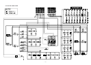
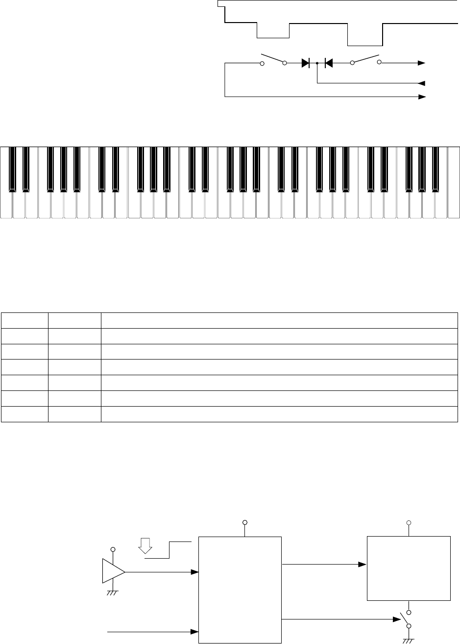
Key
Second contact (2)
First contact (1)
FI
KC
SI
Reset IC
IC105
RE5VA35AA
DSP
LSI101
HG51B227FB
VDD
Reset signal
VDD
Battery set
RESET
VDD
POWER
From power switch
NMI
APO
PLE
CPU
LSI105
UPD912GF-3BA
SCKO
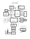
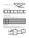
Note: Each key has two contacts,
the first conatct (1) and second contact (2).
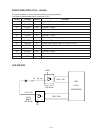
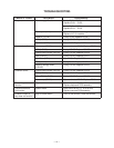
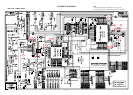
POWER SUPPLY CIRCUIT
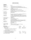
The power supply circuit generates six voltages as shown in the following table. VDD voltage is always
generated. The others are controlled by APO signal from the CPU.
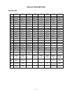
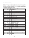
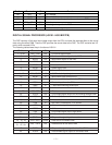
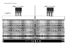
NOMENCLATURE OF KEYS
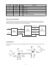
RESET CIRCUIT
When batteries are set or an AC adapter is connected, the reset IC provides a low pulse to the CPU. The
CPU then initializes its internal circuit, and clears the working storage RAM.
When the power switch is pressed, the CPU receives a low pulse of POWER signal. The CPU sends
APO signal to supply ground source for the DSP, also sends a reset signal to the DSP.
Name Voltage For operation of
VDD +5 V CPU, Reset IC, DSP, Sound source ROM, Working storage RAM, Effect RAM
DVDD +5 V Power jack, Sustain jack, MIDI jack
AVDD +5V DAC, Filter
LVDD +4.5 V LED Driver
VCC +9 V Power amplifier, Pilot lamp
VC +9 V Power amplifier
F#3 G#3
A#3 C#4 D#4
F#4 G#4
A#4
C#5
D#5
F#5 G#5
A#5
F3 G3 A3 B3 C4 D4 E4 F4 G4 A4 B4 C5 D5 E5 F5 G5 A5 B5
C6
D#3
C2 D2
E2
F2
G2
A2 B2 C3 D3
E3
B6A6G6F6E6D6
C7
C#3A#2G#2
F#2D#2
C#2
A#6
G#6F#6D#6
C#6