


— 7 —
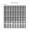
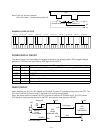
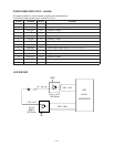
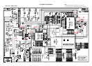
DIGITAL SIGNAL PROCESSOR (LSI101: HG51B227FB)
The DSP receives 16-bit serial sound data output from the CPU and adds the selected effect to the sound
data using the effect RAM. Then the DSP provides the sound data to the DAC. The DSP contains two I/O
ports, which controls LEDs.
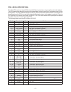
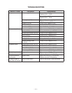
The following table shows the pin functions of LSI101.
Pin No. Terminal In/Out Function
80 VCC In +5 V source
81 GND In Ground (0 V) source
82 MRDB Out Read enable signal output for the sound source ROM
83 ~ 98 MD0 ~ MD15 In/Out Data bus
99 PLE Out Reset signal output for the DSP
100 P17 In APO cancellation signal input
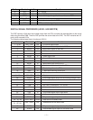
Pin No. Terminal In/Out Function
1 ~ 4, 80 PB0 ~ PB4 Out LED drive signal output
5 SO Out Serial sound data output for the DAC
6 WCKO Out Word clock output for the DAC
7 VDD3 In +5 V source
8 TEST — Not used.
9 RESB In Reset signal input
10 VSS2 In Ground (0 V) source
11, 12 XIN, XOUT In/Out 16 MHz clock input/output
13 WCKI In Word clock input from the CPU
14 SI In Serial sound data input from the CPU
15 BCKI In Bit clock input from the CPU
16 SINC In 1 MHz synchronizing pulse input
17 VDD2 In +5 V source
18 ~ 25 IO0 ~IO7 In/Out Data bus
26 RCEB Out Chip enable signal output for the working storage RAM
27 VSS3 In Ground (0 V) source
28 AD1 In Address bus
29 OEB In Not used. Connected to +5 V source.
30 WEB In Write enable signal input
31 VDD3 In +5 V source
32 CE2 In Chip enable signal input. High active.
33 AD0 In Address bus
34 CE1B In Chip enable signal input. Low active.
35 ~ 41, 43 EIO0 ~EIO7 In/Out Data bus for the effect RAM
42 , 44, 46 ~ 48,
51 ~57, 59
EA0 ~ EA12 Out Address bus for the effect RAM
45 ECEB Out Chip enable signal output for the effect RAM
49 EOEB Out Read enable signal output for the effect RAM