


— 8 —
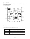
Digital Signal Processor (HG51A115A01FD)
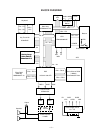
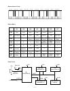
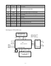
Upon receipt of note numbers and their velocities, the DSP reads sound and velocity data from the sound
source ROM in accordance with the selected tone; the DSP can read rhythm data simultaneously when a
rythm pattern is selected. Then it provides 16-bit serial signals containing data of the melody, chord, bass,
and percussion to the DAC. The DSP also adds the selected effect to the sound data using a 256k-bit
RAM.
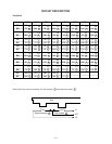
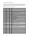
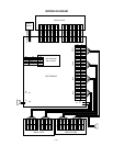
The following table shows the pin functions of the DSP.
Pin No. Terminal In/Out Function
1 ~ 8 CD0 ~ CD7 In/Out Data bus
9, 10 Not used.
11 GND7 In Ground (0V) source
12 CK16 Out 16.384MHz clock output
13 VCC6 In +5V source
14 CK0 In Clock input. Connected to terminal CK16.
15 TCKB Not used.
16 VCC1 In +5V source
17 GND1 In Ground (0V) source
18, 19 XT0, XT1 In/Out 16.384MHz clock input/output. Connected to a crystal oscillator.
20 SGL In System control terminal. Single chip system: Open
21 CCSB In Chip select signal input
22 ~ 25 CA0 ~ CA3 In Addess bus
26 CE0 In Not used. Connected to ground.
27 CWRB In Write enable signal
28 CRDB In Read enable signal
29 ~ 32 Not used.
33 RESB In Reset signal input
34 TESB In Not used. Connected to +5V.
35 ~ 39 Not used.
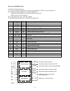
40 ~ 49
52 ~ 57
RD0 ~ RD15 In Data bus for the sound source ROM
58 RA23 Out Not used.
59 RA22 Out Chip select signal for the sound source ROM
60, 61 RA20, RA21 Out Not used.
62 ~ 73
75 ~ 82
RA0 ~ RA19 Out Data bus for the sound source ROM
74 GND5 In Ground (0V) source
83 WOK2 Out Word clock output. Not used.
84 VCC3 In +5V source
85 GND3 In Ground (0V) source
86 WOK1 Out Word clock for the DAC
87 SOLM Out Serial data output. Not used.
88 SOLP Out Serial data output for the DAC
89 BOK Out Bit clock output for the DAC
90 ~ 92 Not used.