


— 12 —
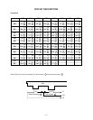
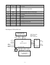
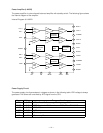
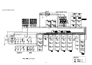
Power Amplifier (LA4620)
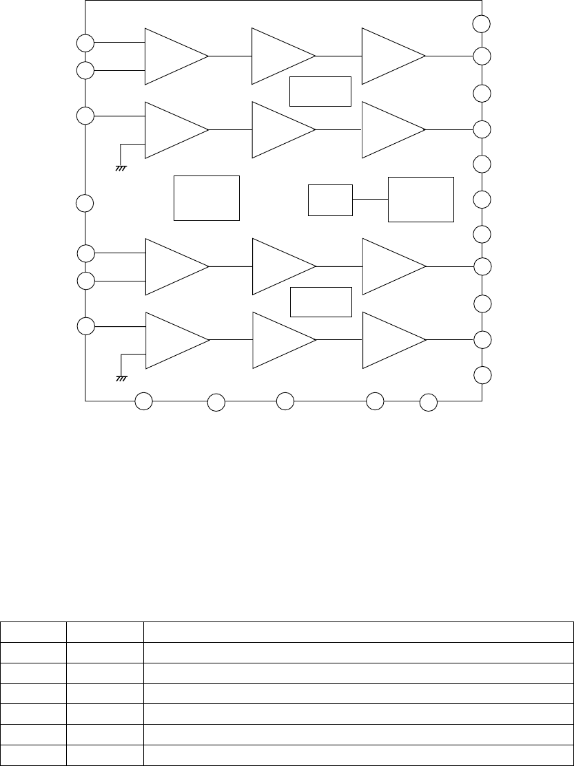
The power amplifier is a two-channel balanced amplifier with standby switch. The following figure shows
the internal diagram of the amplifier.
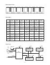
Internal Diagram of LA4620
Input
Amp.
Pre-drive
Amp.
Power
Amp.
RL Short
Protector
Input
Amp.
Pre-drive
Amp.
Power
Amp.
Terminal
Protection
Circuit
Ripple
Filter
Pop Noise
Prevention
Circuit
Input
Amp.
Pre-drive
Amp.
Power
Amp.
RL Short
Protector
Input
Amp.
Pre-drive
Amp.
Power
Amp.
16
10
11
13
2
12
14
15
17
18
1
23
22
21
20
19
3
5
4
9
7
8
6
IN11+
IN11-
IN12-
PriGND
IN21+
IN21-
IN22-
NC DC MUTE VCC2 ADJ
Boot22
OUT22
PoGND2
OUT21
Boot21
VCC1
Boot21
OUT12
PoGND1
OUT11
Boot11
+
-
-
+
+
-
-
+
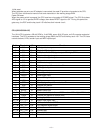
Power Supply Circuit
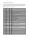
The power supply circuit generates six voltages as shown in the following table. VDD voltage is always
generated. The others are controlled by APO signal from the CPU.
Name Voltage For operation of
VDD +5.1V CPU, Reset IC, Gate array, Working strage RAM
DVDD +5.3V DSP, Key touch LSI, Sound source ROM, Effect RAM, DAC
AVDD +5.2V DAC, Filter
LVDD +5.2V LED driver
VCC +12V Pilot lamp
VD +12V Power amplifier