


— 11 —
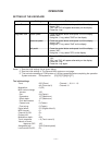
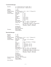
CPU (LSI106: HD6433298A42F)
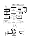
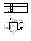
The 16-bit CPU contains a 32k-bit ROM, a 1k-bit RAM, seven 8-bit I/O ports, an A/D convertor and MIDIl
interfaces. The CPU accesses to the working storage RAM, the DSP and the key touch LSI. The CPU
interprets MIDI message using the working storage RAM. The CPU also controls buttons and LEDs.
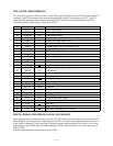
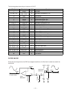
The following table shows the pin functions of LSI106.
Pin No. Terminal In/Out Function
1 P50/TXD Out MIDI signal output
2 P51/RXD In MIDI signal input
3 P52/SCK Out Reset signal output
4 -RESET In Reset signal input
5 -NMI In Power ON trigger signal input
6 VCC In +5V source
7 -STBY In Standby signal input. Connected to +5V.
8 VSS In Ground (0V) source
9, 10 XTAL, EXTAL In 20MHz clock input
11, 12 MD1, MD0 In Mode selection input
13 AVSS In Ground (0V) source
14 P70 In Analog input terminal for the pitch bend wheel
15 P71 In APO cancellation signal input
16 P72 Not used. Connected to +5 V source.
17 ~ 21 P73 ~ P77 Out LED drive signal output
22 AVCC In +5V source
23 ~ 30 P60 ~ P67 Out LED drive signal output
31 VCC In +5V source
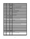
32 P27 Not used
33 ~ 48 A0 ~ A14 Out Address bus
40 VSS In Ground (0V) source
49 ~ 56 D0 ~ D7 In/Out Data bus
57 P40 Out Clock for KO signal generator
58 P41 Out KO signal data
59 P42 Out APO signal output
60 P43 Out Read enable signal output
61 P44 In Write enable signal output
62 P45 Not used
63 P46 Out 10 MHz clock output
64 P47 Not used. Connected to +5 V source.
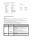
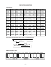
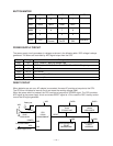
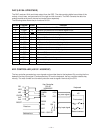
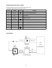
DIGITAL SIGNAL PROCESSOR (LSI102: HG51B155FD)
Upon receipt of note numbers and their velocities, the DSP reads sound and velocity data from the sound
source ROM in accordance with the selected tone; the DSP can read rhythm data simultaneously when a
rythm pattern is selected. Then it provides 16-bit serial signal containing data of the melody, chord, bass,
and percussion to the DAC. When an effect selected, the DSP adds the effect to the sound data using a
256k-bit RAM.
The following table shows the pin functions of LSI102.