


E-34
Getting Ready
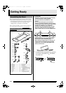
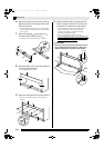
6.
After ensuring that all of the screws are fully
tightened, remove the packing material and
stand up the stand.
• After standing up the stand, cover each of the eight
screws you have installed up to this point with the
screw caps
G
.
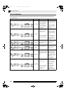
7.
Attach the brackets
M
to the pedal unit
E
and secure them with the screws
J
.
• Cover the screw heads with the screw caps
O
.
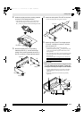
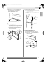
8.
Attach the pedal unit
E
to the side panels
A
and
B
as illustrated below.
• Do not tighten the screws yet.
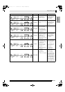
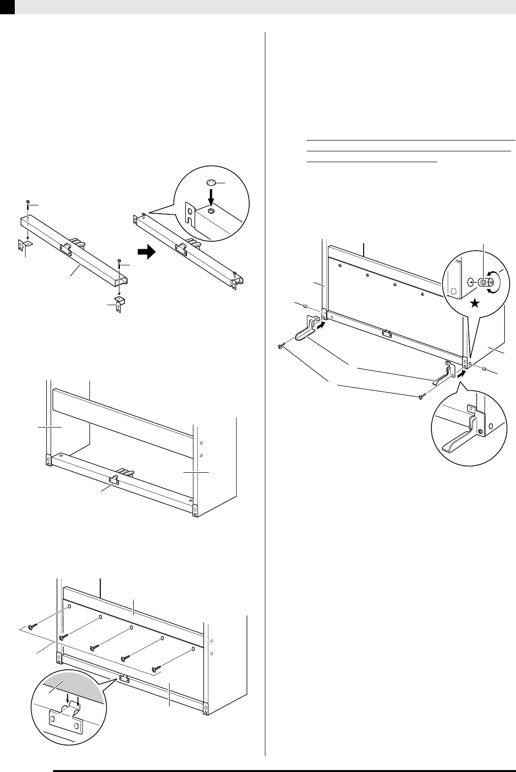
9.
Secure the back panel
D
to the back panel
C
.
•
Screw the screws
I
into the five holes in the back
panel
D
.
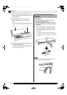
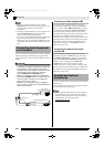
10.
Attach the brackets
N
to the side panels
A
and
B
. Use the two screws
H
and two joint
connectors
P
to attach each side bracket.
• First, insert the joint connectors
P
into the side
panels. At this time, make sure that the joint
connector screw hole is oriented horizontally
(openings to the left and right).
• Secure the brackets
N
with the screws
H
.
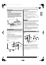
If you have trouble inserting a screw
H into the joint
connector P screw hole, use a screwdriver to rotate
the joint connector (
in Figure).
*
CAUTION
• Never try to force the screws! Forcing a screw
H
to turn while the joint connector
P
hole is not
aligned correctly can strip the screw threads.
M
-(b)
M
-(a)
E
J
J
O
A
B
E
I
5
X
C
D
D
N
H
P
A
B
P
Screw hole
PX830_03_e.fm 34 ページ 2009年7月17日 金曜日 午前10時50分