


p.15
Mono Input channel
1
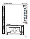
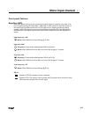
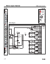
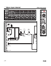
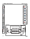
Rear panel features
+48 V On
+48 volts DC is applied equally (thru current-limiting resistors) to both pins 2 and 3 on the mic-
input XLR connector.This feature is used with condenser microphones and active direct boxes that
require an external DC voltage (phantom power) in order to operate. For dynamic or ribbon mics,
phantom voltage is not required and should be switched OFF.
NOTE 1: Operating this switch (On or Off) causes large voltage swings to occur at the input of the
mic preamp. Care should be taken to insure that the channel is muted or the main faders are pulled
down to prevent this POP from getting to someone’s ears.
NOTE 2: Pin-1 of the XLR is used as the DC return path for the phantom voltage. If the Pin-1 Lift
switch is depressed (see below), this path is broken and the microphone will no longer receive oper-
ating power from the XRM. If the Pin-1 Lift switch must be used (to prevent a ground-loop hum or
other unpleasant sounds when connecting to another mixer), then phantom power must be derived
from a different source; either the other connected mixer (usually FOH) or an external phantom sup-
ply.
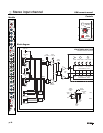
Line Input jack
Line-level signals, balanced or unbalanced, may be brought into the input channel through this
1/4” TRS jack.The LINE switch (front panel) must be pressed for this jack to be active. On the XRM,
the XLR jack is normal'd to the switching contacts of this jack. If nothing is plugged into the jack, a
padded XLR signal is available to the channel when the LINE switch is depressed.This allows the LINE
switch to perform a dual function:XLR pad if nothing is plugged into the Line jack, or XLR(Mic)/Line
input selection if the jack is being used.
Tip is Positive Input,Ring is Negative Input, Sleeve is Chassis Ground
Input impedance is 20KΩ balanced.
XLR(Mic) Input jack
This balanced, latching, female XLR accepts a low-impedance microphone signal, or a line-level
signal, depending on the position of the LINE INPUT switch on the front panel.
Pin-2 is Positive Input,Pin-3 is Negative Input, Pin-1 is Chassis Ground
Input impedance is 4KΩ balanced
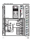
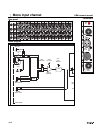
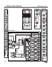
Pin-1 Lift Switch
Pin-1 of both of the XLR jacks is connected to the XRM chassis thru this switch.
This Pin-1 connection serves two main functions:
1) A shield connection point that allows any interference signals (picked up by the cable shield) to be
effectively shunted to ground, thus avoiding signal degradation.
2) A DC return path for the +48 volt phantom power voltage.
Normally, this switch is left in the UP position; Pin-1 is tied to the XRM chassis, and the shielding and
phantom power are both maintained.When the XRM is used by itself, there is usually no reason to
press this switch.When the XRM is used in conjunction with another mixer,either by using the built-
in passive splitter, or when fed from an external splitter, there may be situations where ground differ-
ences between mixers can cause a “ground-loop”.This usually manifests itself as a low-freq hum (usu-
ally at the AC mains freq), a hi-freq buzz,or a combination of both. In most cases, lifting the ground
connection between mixers can clean up this interference.
Pin-1 of BOTH XLR jacks is connected to Chassis ground.
Pin-1 of BOTH XLR jacks is disconnected from Chassis ground.
NOTE 1: The pin-to-pin wiring between the paired XLR connectors is never changed by this switch,
it only disconnects the common, Pin-1 of the XLRs from the mixer chassis, never from one another.
NOTE 2: Remember- if this switch is depressed, it prevents the XRM phantom power from reaching
the attached microphone. Phantom power (if needed) must be supplied from an alternate source.