


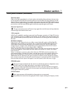
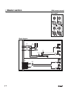

Rear panel features
Main Outputs 1 thru 12
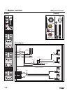
The XRM has 12 Mix outputs. Each output features the following connectors:
Bus Input
Mix Insert
Main Out
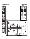
Bus Input
Each of the 12 mixes has an associated Bus Input jack.This female XLR allows external signals
to be mixed into the XRM, either from another X-Rack mixer, or any other audio source.
Electronically balanced input: 20KΩ impedance
Pin-2 Hot, Pin-3 Cold, Pin-1 Chassis
Nominal input level is +4dBu
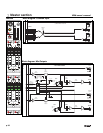
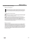
Mix Insert
This switching 1/4” TRS jack allows an external processor to be inserted into the signal
path of the mix bus.The tip carries the SEND signal from the XRM, and the ring carries the RETURN
signal back to the XRM.The insert-send point is located directly after the Lo-Cut filter on the output,
the return comes back at the top of the master fader.
Tip is Send, Ring is Return, Sleeve is Audio Ground.
Send (output) impedance is 100Ω unbalanced
Return (input) impedance is 5KΩ unbalanced
Nominal Operating Level= -2dBu
NOTE: To avoid any degradation of the XRM’s output signal,any processing gear patched into the
mix insert should have a low impedance output (<100Ω) and must be capable of cleanly driving a
2KΩ load to +21dBu.
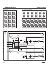
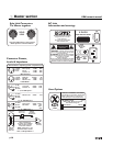
Mix Output
This male XLR is the main output feed for each of the 12 mixes.The jacks are physically
arranged for ease of identification when wiring stereo pairs.The output can be used either balanced
or unbalanced. For unbalanced operation, connect Pin-3 to Pin-1 and take the output from Pin-2.
Electronic balanced cross-coupled output: 100Ω impedance (50Ω per leg)
Pin-2= Hot, Pin-3= Cold, Pin-1= Chassis
Nominal output level is +4dBu.
T= Send
R= Return
S= GND
Master section
3
p.35