


Commercial Audio Series Mixer-Amplifi ers
Operation Manual page 11
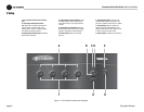
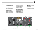
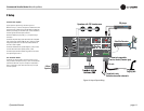
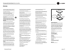
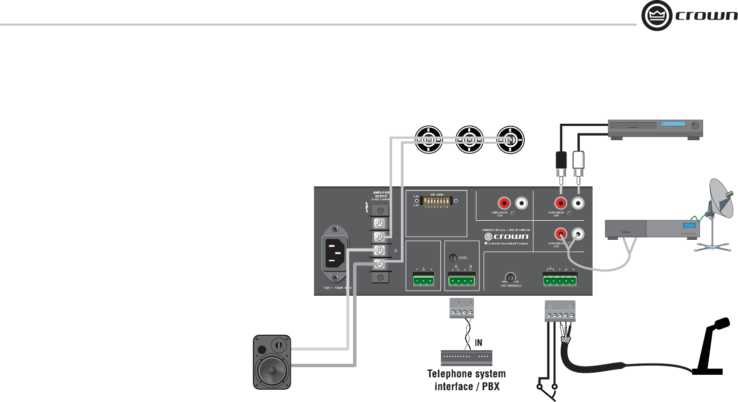
2.4 Wire Your System
Typical input and output wiring is shown in Figure 2.9.
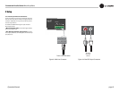
INPUTS: For Input 1, connect a microphone or balanced line-level
signal to the Input 1 balanced input. Set the Mic/Line switch (DIP
switch #1) accordingly. For the other inputs, connect unbalanced
line-level signals to the RCA input connectors.
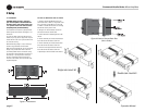
OUTPUTS: Maintain proper polarity (+/–) on amplifi er output
connectors.
Connect the Amplifi er Output screw terminals to the loudspeaker
loads. Use terminals marked COM and 70V or 100V for constant-
voltage loudspeaker loads. Use terminals marked COM and 8
ohms for an 8-ohm speaker.
Connect the COM terminal to speaker negative (–) lead; connect
one of the other terminals to speaker positive (+) lead.
Cover the output connections with the supplied clear non-touch
cover by sliding the cover on.
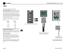
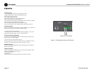
2.6 Phantom Power
Condenser mics require phantom power to operate. If you are
using a condenser microphone on Input 1, turn on DIP switch #8
on the back of the mixer-amp. The microphone must be able to
work on 15V phantom power, which the mixer-amp’s mic input
connector provides.
2 Setup
Figure 2.9 Input-Output Wiring
100V
70V
8
COM
TELEPHONE
(MOH)
PREAMP
OUTPUT
8 600
Input 3Input 4
Input 2
Input 1
1 - CH1
MicOn/LineOff
2 - CH1 Normal
3 - CH1 Priority
4 - CH1 VOX
5 - CH1 to MOH
6 - CH2 to MOH
7 - CH3 to MOH
8 - Phantom
PRIORITY
Speakers with 70V transformers
+
–
+
–
CD player
To switch in mic.
Switch mutes other channels.
To mic
5-terminal removable
barrier block (Phoenix-type)
8-Ohm
Speaker
Satellite Receiver
Paging mic