


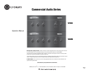
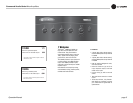
Commercial Audio Series Mixer-Amplifi ers
Operation Manual page 7
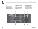
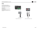
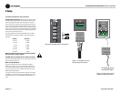
2 Setup
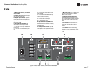
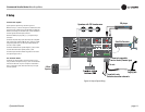
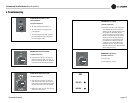
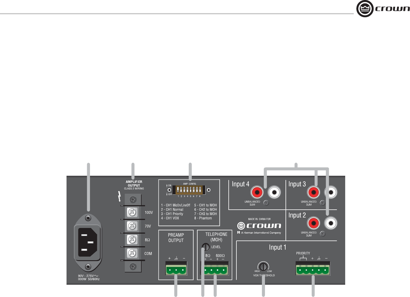
Figure 1.2 Back Panel Controls, Connectors and Indicators
1.3 Back Panel Controls, Connectors
and Indicators
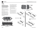
A. AC Power Inlet: Detachable IEC accepts
US or Euro style power cords.
B. Amplifi er Output Connector: 4-position
terminal barrier block with COM (Common),
8 ohms, 70V and 100V terminals. Accepts
up to 10 AWG terminal forks. Clear non-
touch cover included.
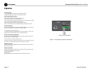
C. Amp Confi guration DIP Switch: DIP
switch selection for multiple functions.
1. On: Sets CH1 to Mic Input. Off: Sets CH1
to Line Input.
2. On: Sets CH1 to Normal mode (no prior-
ity).
3. On: CH1 priority contact closure mutes
other channels.
4. On: CH1 VOX mutes other channels by
sensing signal through Input 1.
5. On: Routes CH1 to MOH output.
6. On: Routes CH2 to MOH output.
7. On: Routes CH3 to MOH output.
8. On: 15V phantom power.
D: Input Connectors 2-4 (160MA) or 2-3
(135MA)
Unbalanced line-level RCA-type connectors,
summed to mono.
E. Preamp Line Out Connector: 3-pin bal-
anced Phoenix-type for connection to exter-
nal amplifi ers. Level independent of master
volume control.
F. MOH Level Control: Trim pot adjusts level
for Music-On-Hold output from Telephone
(MOH) Output Connector.
G. Telephone (MOH) Output Connector:
4-terminal Phoenix connector (2 terminals
for 1W output to 8-ohm speaker, 2 terminals
for 600-ohm output to PBX music-on-hold
port).
H. VOX Threshold: Trim pot controls how
loud the voice on CH1 must be before
muting other channels. Can be set for no
muting.
I. Input Connector 1: 5-terminal Phoenix
connector. 3 terminals for balanced signal, 2
terminals for priority contact closure, which
mutes other channels when DIP switch 3
is on.
A
B
C
D
E
G
H
I
F