


6
ENGLISH
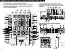
!0 CROSSFADER ASSIGN switch
A, B:
• The channel source is assigned to A or B of the
Crossfader.
POST:
• Select when you don’t assign the channel
source into the Crossfader.
!1 EFFECTS ASSIGN switch
• Use this to select the source of the internal
Effector.
!2 MODE PARAMETER knob
• Use this to set the effect mode and parameters.
!3 EFFECTS WET/DRY control
• Use this to adjust the ratio of original and
effected sound.
!4 EFFECTS ON/OFF button
• Use this to switch the internal Effector function
ON and OFF.
!5 TAP button
• TAP:
When you push this button repeatedly, the
AUTO mode turns off and starts measuring your
Beats Per Minute (BPM) by tapping.
• LOCK:
When this button is pressed once while the
auto BPM counter is operating, the data
measured by the auto BPM counter is locked.
• AUTO:
When pushing the TAP button for 1 second,
activates AUTO BPM mode.
The measured BPM is displayed in the BPM
display.
• INPUT BPM:
When the TAP button is pressed and held in for
more than 2 seconds, the BPM input mode is
set and the BPM value can be input directly with
the MODE PARAMETERS knob !2. When the
button is pressed again, the BPM input mode is
turned off.
!6 CUE buttons
•Pressing in any or all of the CUE buttons routes
the respective source to the headphone and
meter cue sections. Pressing multiple buttons
makes it possible to derive mixed sound from
the selected sources.
!7 CROSSFADER START A, B switches
• Use this to switch the Crossfader Start function
ON and OFF.
!8 Crossfader
• Controls the relative output level from the
summed A and B Mixes. When the fader is at its
far left, only the A Mix is heard from the
outputs. As the fader is moved toward the right,
the amount of B Mix is increased and the
amount of A Mix is decreased. When the fader
is centered, equal amounts of A and B Mixes
are routed to the outputs. Fully right is all B Mix
at the outputs.
!9 Source input fader (Ch. Fader)
• Controls the level of the selected Input.
@0 CROSSFADER CONTOUR control
• Allows adjusting the “shape” of the Crossfader
response from a gentle curve for smooth, long
running fades, to the steep pitch required for
top performance cut and scratch effects.
@1 HEADPHONE output jack
•Accepts 1/4” stereo headphone plugs.
@2 HEADPHONE LEVEL control
• Adjusts the volume for the headphones.
@3 HEADPHONE PAN control
• Serves two purposes…In the STEREO mode it
changes the relative levels of the Cue and
Program (CUE MASTER) mixed together in both
earcups. In the SPLIT CUE (MONO) mode it
changes the balance between the Mono Cue in
the left ear cup and the Mono Program
(MASTER) in the right.
@4 SPLIT CUE button
• In the STEREO mode, this button feeds
STEREO Program (CUE MASTER) and Cue to
both earcups, in the SPLIT CUE (MONO) mode,
the headphone circuit provides MONO Cue to
the left ear and MONO Program (MASTER) to
the right.
• In the STEREO mode, the meter indicates the
stereo level in the LEFT and RIGHT Master
Outputs. In the SPLIT CUE (MONO) mode,
mono Cue level is displayed on the Left meter
and mono Program (CUE MASTER) level is
displayed on the Right meter.
• In the SPLIT CUE (MONO) mode, the button is
lit.
@5 EFFECT LOOP WET/DRY control
• Use this to adjust the ratio of original and
effected sound.
@6 CH FADER START switch
• Use this to switch the Channel Fader Start
function ON and OFF.
@7 EFFECT LOOP ASSIGN switch
• Use this to select the source of the external
processor.
@8 EFFECT LOOP ON/OFF button
• Routes the assigned signal through the external
processor attached to the SEND/RETURN
connectors on the rear.
• When the EFFECT is ON, the button is lit.
(When the processor isn’t connected, the
button will blink when activated.)
@9 TALK OVER ON/OFF button
• Use this to switch the Talk Over function ON
and OFF.
• When the button is lit, level of signals except
Mics is attenuated.
• The Talk Over attenuation level can be adjusted
in the Preset mode.
NOTE:
When this button is pushed, volume changes
rapidly.
#0 MIC POST ON/OFF button
• Puts the Mic signals into the BOOTH, REC and
DIGITAL out signal path.
#1 MIC EQ controls
• Contour the frequency response of the MIC
input –12 dB to +12 dB.
At the center position, sound is flat.
#2 MIC LEVEL controls
• Adjusts the level of the Mic signal.
#3 MIC ON/OFF buttons
• When the button is lit, Mic signal is transferred
to output section, otherwise Mic input is muted.
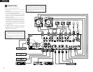
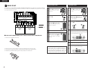
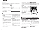
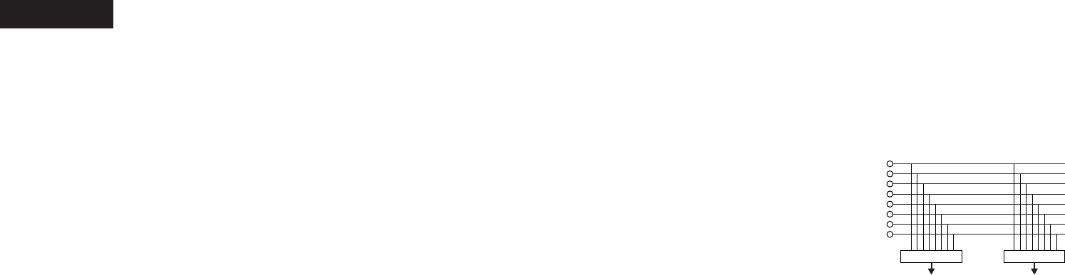
#4 INPUT ASSIGN (Input selectors)
• Select any source from eight inputs
(PHONO1/LINE1, LINE2, PHONO2/LINE3,
LINE4, PHONO3/LINE5, LINE6, LINE7, LINE8)
for each channel independently.
•You also can assign the same input to several
channels for creative mixing.
#5 GAIN (Line input level controls)
• Adjusts the level of the selected input.
•You can adjust each GAIN volume to indicate
0dB on source level meter.
#6 Source EQ controls
• Contour the frequency response of the selected
inputs.
At the center position, sound is flat.
HI and MID:
• Adjusts the high-tone and mid-tone sound –40
dB to +10 dB.
LOW:
• Adjusts the low-tone sound –40 dB to +6 dB.
NOTE:
Clipping may occur if adjustments are set to
harsh.
#7 CUE MASTER level meter
• Displays the output level following MASTER
LEVEL adjustment.
• Can switch between two display mode. See
below @4.
#8 Source level meters
• Displays the input level after adjusted with
GAIN #5 and EQ #6 controls.
NOTE:
If this meter indicates over +12 dB, inputted
sound may be clipped.
#9 EQ ON/OFF buttons
• When this button is lit EQ is on, otherwise EQ is
bypassed.
LINE1
LINE2
LINE3
LINE4
LINE5
LINE6
LINE7
LINE8
• • • • •
INPUT ASSIGN INPUT ASSIGN
CH1 CH4