


Instruction Manual
IM-106-340AC-1, Rev. 1.0
April 2005
SPS 4001B
2-4
ELECTRICAL
CONNECTIONS
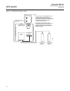
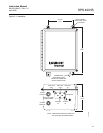
All wiring must conform to local and national codes. Use the following
procedure to connect an SPS 4001B to an Oxymitter 4000.
NOTE
Ensure the Oxymitter 4000 is set up to handshake with the sequencer by
configuring the logic I/O to mode 8. Refer to the Oxymitter 4000 Oxygen
Transmitter Instruction Manual for more information.
NOTE
To maintain proper earth grounding, ensure a positive connection exists
between the ground lug and earth.
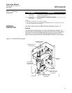
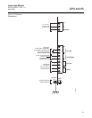
1. Loosen the SPS 4001B cover screws and open the cover.
2. Route the line voltage cable into the enclosure through the rear cable
grip. Ensure adequate wire length to connect the line voltage leads per
Figure 2-2, then tighten the cable grip nut.
3. Connect the incoming 90 to 250 VAC ±10%, 50/60 Hz line voltage leads
to the terminal strip and ground lug as indicated in Figure 2-2.
4. Route the signal wiring cable through the front cable grip. Ensure
adequate wire length to connect all signal wires per Figure 2-2, then
tighten the cable grip nut. Use shielded twisted pair wiring. Terminate
the shield at the SPS 4001B.
5. Connect the 5V (5 mA maximum) logic I/O leads from the Oxymitter
4000 to the terminal strip as indicated in Figure 2-2. Use shielded
twisted pair wiring. Terminate the shield at the Oxymitter 4000.
6. To set up the SPS 4001B to initiate a calibration from a remote location,
connect the 5 VDC input leads to the terminal strip as shown in
Figure 2-2.
7. Relay output connections are available on the unit to signal when the
Oxymitter 4000 is in calibration or when calibration failed. Relay outputs
can be connected to either indicator lights or a computer interface. The
relay contacts are capable of handling a 5 to 30 VDC maximum power
source. The cabling requirement is 1000 ft (303 m) maximum. Connect
the relay output wires to the terminal strip as shown in Figure 2-2. Use
shielded twisted pair wiring. Terminate the shield at the SPS 4001B.
8. Once all connections are made, close the enclosure cover and tighten
the cover screws.
Disconnect and lock out power before connecting the unit to the power supply.