


Instruction Manual
IM-106-340AC-1, Rev. 1.0
April 2005
4-5
SPS 4001B
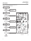
CIRCUIT BOARD
REPLACEMENT
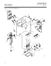
Perform the following procedure to replace circuit board (5, Figure 4-1).
1. Remove the SPS 4001B chassis from the enclosure according to the
instructions in "Remove/Install Chassis".
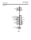
2. Refer to Figure 4-2. Disconnect wiring from the circuit board.
3. Disconnect the solenoid and pressure switch connectors.
4. Refer to Figure 4-1. Remove circuit board (5) from chassis (24).
5. Connect mating wires to solenoid (14 or 15) and pressure switch (16).
Lo Gas solenoid connects to J6, Hi Gas solenoid to J5, and pressure
switch to J3.
6. Install the replacement circuit board (5) on chassis (24).
7. Reinstall field wiring to circuit board.
8. Install the SPS 4001B chassis in the enclosure according to the
instructions in "Remove/Install Chassis".
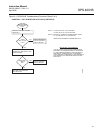
SOLENOID
REPLACEMENT
Use this procedure to replace the calibration gas 1 (Hi Gas) solenoid (14,
Figure 4-1) or calibration gas 2 (Low Gas) solenoid (15).
1. Remove the SPS 4001B chassis from the enclosure according to the
instructions in "Remove/Install Chassis".
2. Unplug solenoid (14 or 15) lead wire.
3. Remove the top nut of solenoid (14 or 15) securing the coil assembly
and washer to the base. Remove the coil assembly, including the leads,
and washer. Use a 13/16 in. wrench to loosen and remove the solenoid
base.
4. Install the new solenoid base. Be careful not to overtighten. Install the
new washer and coil assembly and secure with the top nut.
5. Connect the solenoid lead wire to solenoid (14 or 15).
6. Install the SPS 4001B chassis in the enclosure according to the
instructions in "Remove/Install Chassis".
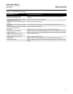
Disconnect and lock out power before working on any electrical components.
Disconnect and lock out power before working on any electrical components.
When installing a solenoid, do not overtighten. Damage to the solenoid may occur.