


Instruction Manual
IM-106-340AC-1, Rev. 1.0
April 2005
SPS 4001B
http://www.raihome.com
Index
A
Accessories . . . . . . . . . . . . . . . 1-3
Ambient Temperature . . . . 1-2, 2-1
B
Bottle Rack . . . . . . . . . . . . . . . . 1-3
C
Cabling Distance . . . . . . . . . . . . 1-2
Cal Failed Relay Contact . . . . . 1-2
Cal Recommended . . . . . . 1-5, 3-3
Calibrated Gas Mixtures . . . . . . 3-2
Calibration . . . . . . . . . . . . . . . . . 1-3
Calibration Components . . . . . . 1-3
Calibration Gas . . . . . . . . . . . . . 2-2
Calibration Gas 1 . . . . . . . . . . . 1-5
Calibration Gas 2 . . . . . . . . . . . 1-5
Calibration Gas Bottles . . . . . . . 1-3
Calibration Gas
Flow Meter . . . . . . . . . . . 1-4, 3-3
Calibration Gas Solenoids . . . . 1-3
Calibration Gas Tanks . . . . . . . . 3-1
Calibration Recommended . . . . 1-3
Certification . . . . . . . . . . . . . . . . 1-2
Check Valve . . . . . . . . . . . 2-2, 3-2
Circuit Board . . . . . . . . . . . . . . . 1-4
Component Checklist . . . . . . . . 1-1
D
Drain Valve . . . . . . . . . . . . . . . . 1-4
E
Electrical Connections . . . . . . . . 2-5
Enclosure Protection . . . . . . . . . 1-2
Essential Instructions . . . . . . . . . . i
Explosion-proof Option . . . . . . . 1-2
External Electrical Noise . . . . . . 1-2
F
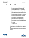
Factory Repair . . . . . . . . . . . . . .B-1
Flow Regulators . . . . . . . . . . . . 1-3
H
Handshake . . . . . . . . . . . . . . . . 2-4
Handshake Mode . . . . . . . . . . . 3-3
Handshake Signal . . . . . . . . . . . 1-2
Humidity Range . . . . . . . . . . . . . 1-2
I
In-cal Relay Contact . . . . . . . . . 1-2
Input Power . . . . . . . . . . . . . . . . 1-2
Instrument Air . . . . . . . . . . . . . . 3-3
Instrument Air Supply . . . . . . . . 2-2
M
Main Components . . . . . . . . . . . 1-3
Manifold . . . . . . . . . . . . . . . . . . . 1-3
Materials of Construction . . . . . 1-2
N
Nema Cabinet . . . . . . . . . . . . . . 1-2
O
O
2
Calibration Gas 1 . . . . . . . . .2-2
O
2
Calibration Gas 2 . . . . . . . . .2-2
P
Part Number . . . . . . . . . . . . . . .1-2
Piping Distance . . . . . . . . . . . . .1-2
Power Consumption . . . . . . . . .1-2
Pressure Regulator . . 1-4, 2-2, 3-3
Pressure Switch . . . . . . . . . . . . .1-4
Programmable Logic Device . . .1-5
R
Reference Air . . . . . . . . . . . . . . .2-2
Reference Air . . . . . . . . . . . . . . .2-2
Reference Air Flow Meter . 1-4, 3-3
Reference Air Pressure
Regulator . . . . . . . . . . . . . . . .3-3
Remote-site Calibrations . . . . . .3-4
Returning Material . . . . . . . . . . B-1
S
Specifications . . . . . . . . . . . . . .1-2
SPS 4001B Calibration Setup . .1-6
SPS 4001B Components . . . . . .1-3
SPS 4001B Package . . . . . . . . .1-1
T
Timed Interval Calibration . . . . .3-3
W
Warranty Service . . . . . . . . . . . B-1