LBI-39055
12
Dispatcher Keyboard
The dispatcher keyboard interfaces to the PC via
circuitry on the Logic Board. Its part number is
P29/7590182002 (344A3927P25). This keyboard is
sometimes referred to as the "custom keyboard".
Connect the dispatcher keyboard to the PC by plugging
its 4-pin interlocking plug to the round socket at the Logic
Board's rear cover plate. If the Logic Board is vertically
orientated, this socket is located just above the female DB-
37 connector. When correctly mated, the red dot on the
plug will be in a 3 o'clock or 9 o'clock position if the Logic
Board is vertically orientated.
If disconnection is necessary, pull on the sleeve and not
on the cable. Pulling on the cable will not free the latch and
may damage the cable if excessive force is used.
Standard PC Keyboard
During dispatch operations, the standard PC keyboard
is not used. However, during the console set-up process,
access to this keyboard will be required:
• for file management (for example -
AUTOEXEC.BAT and CONFIG.SYS file changes
may be necessary)
• to configure certain items via the Editor program
(see LBI-39056 for details)
• to start and operate the CTEST test program
• to start the console's application program
Connect the standard PC keyboard to the PC in
accordance with the manufacturer's instructions.
Video Display Monitor
Interconnect the video display monitor's video cable to
the Personal Computer in accordance with the
manufacturer's instructions.
AUDIO TOWER
All Audio Tower-related cables should be routed out of
the bottom of the case through the cut-out in the bottom of
the rear door. If necessary, some or all of the cables can be
routed under the case's stand and out to the front of the
Audio Tower. Secure the cables with cable ties as
necessary.
Desk Mic (if used)
Connect the desk microphone (option CRMC3D or
equivalent) to the Audio Tower by mating its male DB-9
connector to the female DB-9 connector labeled "DESK
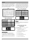
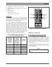
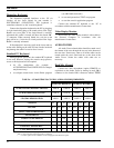
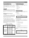
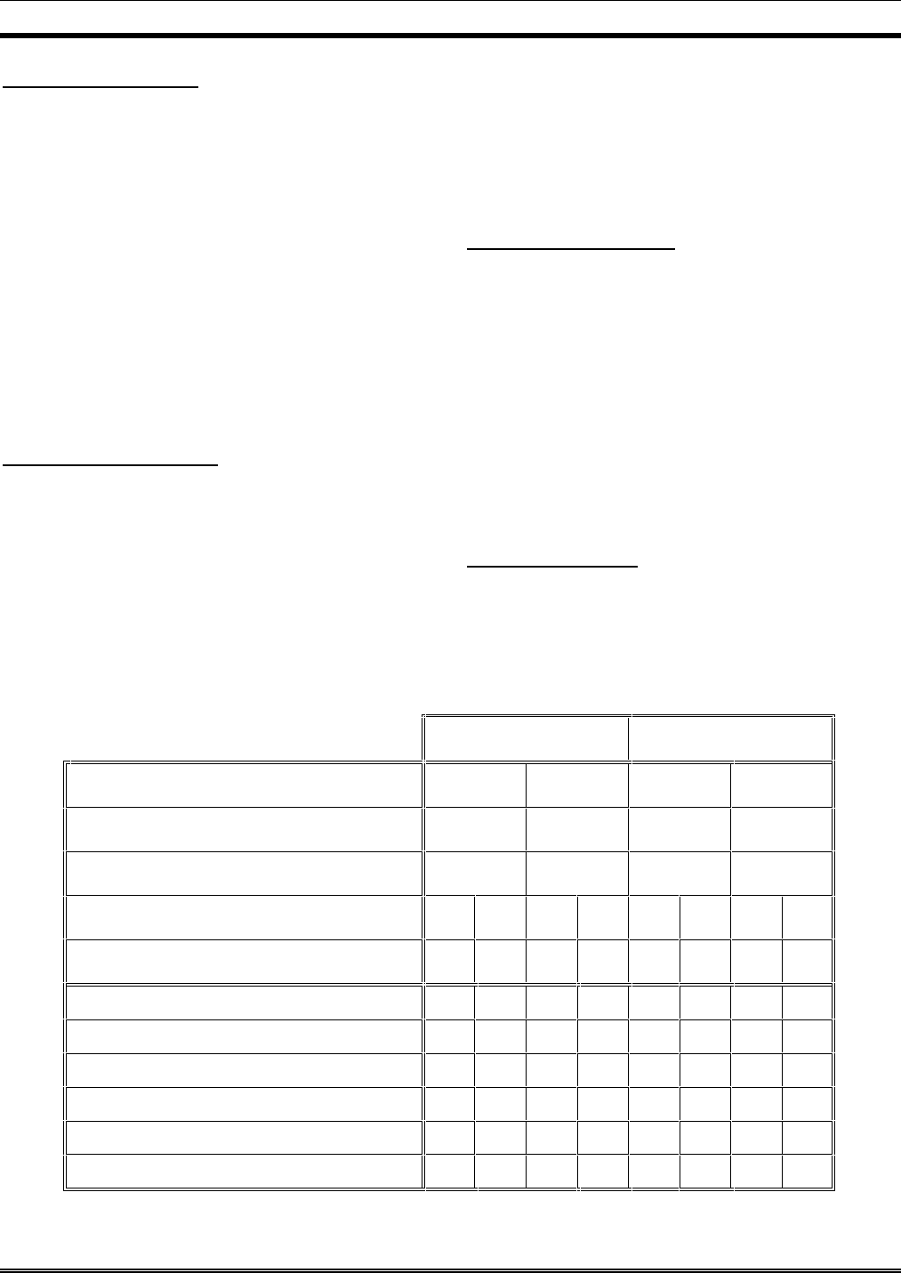
TABLE 6 −− C3 MAESTRO-TO-CEC/IMC AUDIO LINE REQUIREMENTS
AUDIO PA BOARD #1
AUDIO PA BOARD #2
AUDIO MATRIX BOARD LABELING
LINE A LINE B LINE A LINE B
C3 MAESTRO DESIGNATION
LINE A LINE B LINE C LINE D
CEC/IMC DESIGNATION
LINE 1 LINE 2 LINE 3 LINE 4
CONSOLE
IN OUT IN OUT IN OUT IN OUT
CEC/IMC
OUT IN OUT IN OUT IN OUT IN
SELECT SPEAKER/HEADSET
X
MICROPHONE
X
UNSELECT SPEAKER #1
XX
UNSELECT SPEAKER #2
XX
UNSELECT SPEAKER #3 *
XX
CALL DIRECTOR PATCH
XX XX
"X" = 2-wire connection always required
"XX"= 2-wire connection required if console is so equipped
* = Unselect speaker #3 not available if console is equipped with Call Director patch


