LBI-39055
6
amplifiers' source audio from the Audio Matrix Board
(normal) to Line A and Line B balanced inputs (test),
respectively. See LBI-39064 for specific details. With this
test setting, audio signals on the line inputs are applied
directly to the speakers' power amplifiers without being
routed through the Audio Matrix Board.
NOTE
SW2 is not present on Audio PA Board
P29/5000055000. Audio source selection on this
earlier board (sometimes referred to as a "Phase 1"
board) is accomplished via two jumpers/plugs
identified as JP1 and JP2. During normal (non-
test) console operations, jumpers must be in
between pins "A" and "C" on both plugs. These
settings route Line A and Line B audio signals
from the Audio PA Board to the Speaker A and
Speaker B power amplifiers. See LBI-38716 for
additional details.
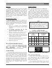
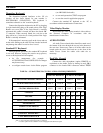
TABLE 3 −− AUDIO PA BOARD
AUDIO SOURCE SELECTION
SW2 POSITION
1234
SOURCE OUTPUT
ON OFF x x Matrix Bd. Speaker A
OFF ON x x Line A In Speaker A
x x ON OFF Matrix Bd. Speaker B
x x OFF ON Line B In Speaker B
"x" = either position
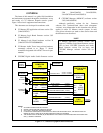
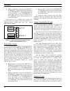
Figure 5 −− Audio PA Board SW2 Factory Setting
Audio Matrix Board
SW1 −− Mic Audio ALC Enable/Disable DIP Switch
DIP switch SW1 on the Audio Matrix Board is used to
independently enable or disable each microphone's
automatic level control (ALC) circuit. The switch has four
(4) positions, one for each mic that may be connected to the
board.
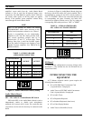
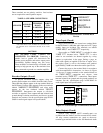
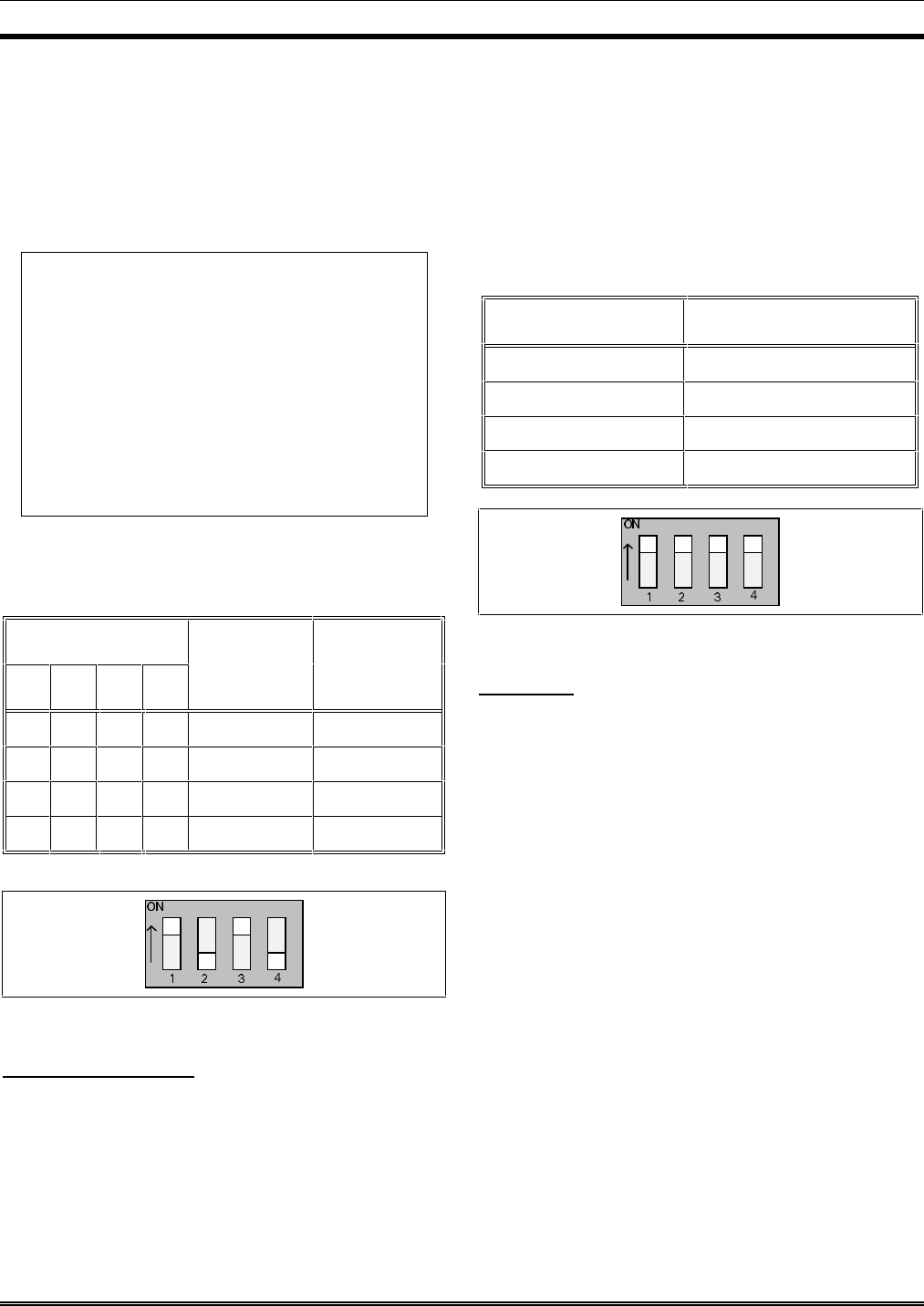
As shown in Figure 6, Audio Matrix Boards ship from
the factory with all mic audio ALC circuits enabled. This is
accomplished by setting all four SW1 switch positions to
"ON" or "CLOSED". Table 4 lists each switch position and
its corresponding mic input. Normally, mic audio ALC
should not be disabled. Disable a mic's ALC by setting the
corresponding DIP switch position to "OFF" or "OPEN".
TABLE 4 −− AUDIO MATRIX BOARD
MIC AUDIO ALC ENABLE/DISABLE
SW1 POSITION MIC
1 Boom/Gooseneck
2 Desk
3 Operator Headset
4 Supervisor Headset
Figure 6 −− Audio Matrix Board SW1 Factory Setting
I/O Board
No I/O Board configuration is necessary. Simply verify
the Board is fully inserted into the far left-hand slot (as
viewed from front).
INTERCONNECTING THE
EQUIPMENT
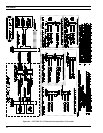
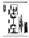
A C3 Maestro dispatch console system requires the
following interconnections:
• PC-to-CEC/IMC Data Concentrator Card
(via punch blocks, if employed)
• Audio Tower-to-CEC/IMC Audio Concentrator
Card (via punch blocks, if employed)
• PC-to-Audio Tower
• PC-to-Dispatcher Keyboard
• PC-to-Standard Keyboard (when in use)
• PC-to-Video Display Monitor
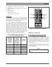
• Audio Tower-to-Desk Mic (if used)


