Issue 3, May 1997 Model 750 User Guide
Page 22 Studio Technologies, Inc.
Model 750
output. Also, if the VU meter source button is set
to follow the monitor section, the AUX bus signals
will automatically be connected to the VU meters
whenever AUX interrupt is active.
8. EXT 2 INPUT LEVEL: 10
▼▼
▼▼
▼
/ +4
▲▲
▲▲
▲
This switch is used to select the nominal input
level of external monitor input 2. In the down
position the nominal input level is 10dBu. In the
up position the nominal input level is +4dBu.
3. REC L ONLY/R ONLY: DISABLE
▼▼
▼▼
▼
/ ENABLE
▲▲
▲▲
▲
This switch selects whether the setup sections
L Only and R Only voice segments can be re-
corded. In the down position recording cannot
take place. In the up position recording can take
place.
This feature can prove useful where semi-
permanent L Only and R Only voice segments
need to be recorded. By placing the switch to the
down position, the L+R voice segment cannot be
changed.
4. SINGLE TONE: 400HZ
▼▼
▼▼
▼
/ 1KHZ
▲▲
▲▲
▲
This switch selects whether the setup sections
single tone feature will generate a 400Hz or a
1kHz sine wave signal. In the down position
400Hz will be generated. In the up position 1kHz
will be generated.
5: MULTI-TONE SEQUENCE: BASIC
▼▼
▼▼
▼
/
ADVANCED
▲▲
▲▲
▲
This switch selects whether the setup sections
multi-tone feature will generate a basic or an
advanced sequence of tones. In the down position
the basic sequence will be generated. In the up
position the advanced sequence will be gener-
ated. Refer to appendices A-1 and A-2 for detailed
descriptions of the tone sequences.
6: AUX INT SPEAKER: NO
▼▼
▼▼
▼
/ YES
▲▲
▲▲
▲
This switch selects whether the AUX audio bus will
automatically be selected as the audio source for
the monitor speaker whenever an input channel or
the setup section is assigned to the AUX bus. In
the down position a signal assigned to the AUX
bus will not impact the monitor speaker output. In
the up position any signal assigned to the AUX
bus will automatically be connected to the monitor
speaker output. Also, if the VU meter source
button is set to follow the monitor section, the AUX
bus signals will automatically be connected to the
VU meters whenever AUX interrupt is active.
7. AUX INT PHONES: NO
▼▼
▼▼
▼
/ YES
▲▲
▲▲
▲
This switch selects whether the AUX audio bus will
automatically be selected as the audio source for
the headphone output whenever an input channel
or the setup section is assigned to the AUX bus.
In the down position a signal assigned to the AUX
bus will not impact the headphone output. In the
up position any signal assigned to the AUX bus
will automatically be connected to the headphone
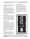
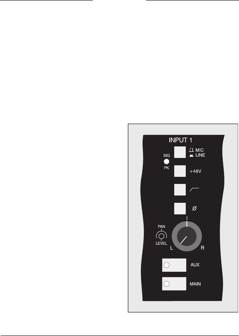
Figure 9. Detail of front panel showing mic/
line input channel (typical of 4)


