Model 750 User Guide Issue 3, May 1997
Studio Technologies, Inc. Page 11
Model 750
Locating the Unit
Physical access and mechanical noise
are the primary factors when choosing a
mounting location. By its very nature as an
audio mixer, an operator will need easy
access to all the controls, as well as good
sight lines to the meters. In most cases the
internal microphone, located on the upper
right side of the front panel, will be used,
so be careful that you dont have a cooling
fan blowing directly onto it.
As a device that contains high gain audio
stages, hum and noise pickup is possible
through the chassis and associated ca-
bling. Locating the unit away from devices
that radiate strong AC fields is an excellent
idea. The left side of the Model 750, which
contains the microphone preamplifiers, is
the area most sensitive to noise pickup.
Also, it is possible that the Model 750s
power transformer may radiate energy into
adjacent equipment. It is located at the
right, bottom rear corner of the unit, and
may need to be physically isolated from
sensitive equipment, especially videotape
recorders.
Mounting
The Model 750 is intended for rack mount-
ing, requiring two standard rack spaces
(3.5 inches). It weights approximately 14
pounds (6.4kg), and operates on either
100, 120, or 200/240V, 50/60Hz. The unit is
secured to the front mounting rails of an
equipment rack using two mounting
screws per side.
Audio Inputs and Outputs
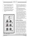
The Model 750s audio input and output
connections are made using 3-pin XLR-
type and ¼-inch 3-conductor phone jacks.
Balanced Connections
(Input & Output)
Sleeve
(Shield)
(Switchcraft No. 297, Neutrik NP3C, or equivalent)
Tip ( + )
Ring ()
Dont be concerned about our use of
phone jacks as part of a professional
product. The jacks used feature gold-
plated contacts for high reliability. As
much as we wanted to, there was simply
no room in only two rack spaces to use all
XLR-type connectors.
Caution: For reliable audio intercon-
nection, the phone plugs you use must
comply with industry-standard RS-453.
Switchcraft No. 297 or Neutrik NP3C
are highly recommended.
Mic/Line Inputs
The Model 750 contains four input chan-
nels that are compatible with microphone
or line-level sources. Each of the four
Mic/Line inputs use a single 3-pin female
XLR-type connector. Prepare the mating
connectors (males) so that pin 2 is signal
high (+ or hot), pin 3 is low ( or cold),
and pin 1 is shield.
It is expected that the mic/line inputs will
be wired to input/output connector panels
located on the side or rear of the vehicle.
Its also nice to have one or two of the
inputs multed to connectors inside the
vehicle, allowing the quick connection of
Figure 3. Recommended phone plugs


