


MB15F74UL
7
(Continued)
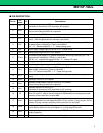
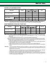
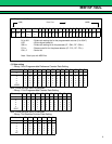
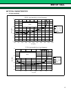
(VCC = 2.7 V to 3.6 V, Ta = −40 °C to +85 °C)
*1 : Conditions ; fosc = 12.8 MHz, Ta = +25 °C, SW = “L” in locking state.
*2 : V
CCIF = VpIF = VCCRF = VpRF = 3.0 V, fosc = 12.8 MHz, Ta = +25 °C, in power saving mode.
PS
IF = PSRF = GND
V
IH = VCC, VIL = GND (at CLK, Data, LE)
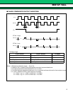
*3 : AC coupling. 1000 pF capacitor is connected under the condition of Min operating frequency.
*4 : The symbol “–” (minus) means the direction of current flow.
*5 : V
CC = Vp = 3.0 V, Ta = +25 °C (||I3| − |I4||) / [ (|I3| + |I4|) / 2] × 100 (%)
*6 : VCC = Vp = 3.0 V, Ta = +25 °C [ (||I2| − |I1||) / 2] / [ (|I1| + |I2|) / 2] × 100 (%) (Applied to both lDOL and lDOH)
*7 : V
CC = Vp = 3.0 V, [||IDO (+85 °C) | − |IDO (–40 °C) || / 2] / [|IDO (+85 °C) | + |IDO (–40 °C) | / 2] × 100 (%) (Applied to both
I
DOL and IDOH)
*8 : When Charge pump current is measured, set LDS = “L” , T1 = “L” and T2 = “H”.
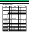
Parameter Symbol Condition
Value
Unit
Min Typ Max
“H” level output
current
Do
IF
*8
DoRF
IDOH
*4
VCC = Vp = 3.0 V,
V
DOH = Vp / 2,
Ta = +25 °C
CS bit = “H” −8.2 −6.0 −4.1 mA
CS bit = “L” −2.2 −1.5 −0.8 mA
“L” level output
current
Do
IF
*8
DoRF
IDOL
VCC = Vp = 3.0 V,
V
DOL = Vp / 2,
Ta = +25 °C
CS bit = “H” 4.1 6.0 8.2 mA
CS bit = “L” 0.8 1.5 2.2 mA
Charge pump
current rate
I
DOL/IDOH IDOMT
*5
VDO = Vp / 2 310%
vs VDO IDOVD
*6
0.5 V ≤ VDO ≤ Vp − 0.5 V 10 15 %
vs Ta I
DOTA
*7
−40 °C ≤ Ta ≤ 85 °C,
V
DO = Vp / 2
510%
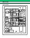
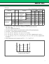
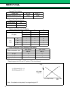
IDOL
I1
I3
I2
I1
I4
I2
0.5 Vp/2 Vp − 0.5 Vp
I
DOH
Charge pump output voltage (V)