


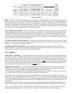
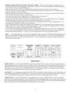

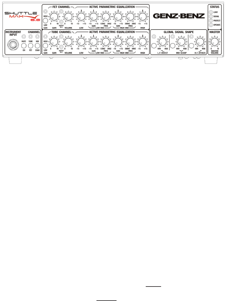
FRONT PANEL
INPUT – The SHUTTLE MAX 6.0 is equipped with a standard ¼” unbalanced INPUT. The INPUT sensitivity range is
from 40 mV to over 1.6 volts. The INPUT impedance is >500K ohms. The INPUT stage contains a precision high order
active high pass lter (more effective and less intrusive than the more common 6 dB lters) and an “RFI” lter (radio
frequency interference) to eliminate unwanted noise. The INPUT gain stages consist of a feedback type variable gain
circuit that provides wide range, continuously variable gain with minimal noise. The preamp contains an FET input amp
circuit based on our highly regarded GBE series touring ampliers.
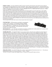
INPUT SIGNAL MUTE SWITCH – With this MUTE switch, you can place the amplier (and Direct Output) in standby
mode between sets, without having to change any of your amp settings. This feature can also be used for silent tun-
ing since the TUNER OUT stays active when the MUTE is engaged. A red LED indicates when the MUTE is active.
This function is not operable from the included 5-button footswitch, but a rear panel jack is provided so a standard
single button footswitch can be used to remotely engage this function. The switch on the amplier’s faceplate must be
in the out position for the footswitch to work properly.
FET/TUBE CHANNEL SELECTOR SWITCH – This switch is provided to select either the FET channel or the TUBE
channel. This function can be remotely engaged via the 5-button footswitch. The front panel switch must be in the out
position for the foot switch to engage the function.
CHANNEL MIX SELECTOR SWITCH – When engaged this switch combines the signal of the FET and TUBE
channels together. This function can also be remotely engaged via the 5-button footswitch. The front panel switch
must be in the out position for the footswitch to engage the function.
FET CHANNEL---
GAIN SWITCH (LOW/HIGH) – This switch sets the GAIN sensitivity for the FET channel. It works somewhat like an
Active/Passive switch. The amber LED indicates that the HIGH setting is selected. The difference between the LOW
and HIGH gain positions is approx. 10dB. Since there is a GAIN Switch provided for each channel this allows the
player to set different gain structures for the FET or TUBE channels. If the cleanest possible signal is desired, we rec-
ommend that the LOW setting be used for basses with hotter output or active pickups (those with an output sensitivity
over 1 Volt, generally most basses using one or two 9 volt batteries to power their on board preamp) and the HIGH
gain setting be used for basses with lower output or passive pickups.
PREAMP GAIN CONTROL – This control sets the GAIN level of the preamp to the output of your bass. If the red
OVERLOAD “O/L” LED ashes when setting up your input levels, reduce the preamp gain control to eliminate any
input preamp overload. You may want to check the setting of the GAIN switch as well.
This GAIN control, in conjunction with the PREAMP VOLUME control allows you to set the signal level to the EQ sec-
tion. The MASTER VOLUME then controls the total output level of the power amp.
“O/L” LED – In the FET channel this LED senses the condition of the input signal after the GAIN control and also
senses and warns of possible clipping in the EQ network. The “O/L” sensing circuit is very dependent upon the output
of the bass instrument pickups, the GAIN and VOLUME level settings of the FET channel and the amount of EQ used
i.e. the more radical the EQ boost and volume level of the PREAMP VOLUME control, the more possibility of an over-
load condition.
If overloading of the FET channel is occurring adjusting the PREAMP GAIN and /or PREAMP VOLUME down will
reduce or eliminate the over-load condition and adjusting the MASTER VOLUME up will return the overall loudness.
Note: It is OK for this LED to ash occasionally with your hardest notes played and it may ash even if the TUBE
channel has been selected for use. This is normal and is due to the mixing topology for the 2 channels.
2