


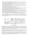

EFFECTS LOOPS – The serial “EFFECTS LOOP” jacks are provided to allow access to the signal for the purpose of
inserting signal processing equipment such as compressors, chorus, delay & reverb processors. Individual pre-EQ loops
are provided for the TUBE channel and the FET channel. An additional MASTER post EQ loop is provided for the summed
(TUBE + FET) signal. This loop may also be used as a PREAMP OUTPUT or POWER AMP INPUT patch point. “SEND”
(output) and “RETURN” (input) are nominal +4 dB level.
“Series” devices (such as compressors and gates) require that the signal ow out from the send jack on the amplier,
through the processing device and back into the return jack on the amplier. Parallel or mixed signal devices (such as
chorus, delay and reverb processors) require that the signal ow out of the send jack on the amplier, through the unit
where it is split into a dry (unaltered) signal and a wet (processed) signal. On the processing unit, you will use the mixed
signal output to return the signals (both wet and dry) to the return jack on the amplier. The ratio between the wet signal
and the dry signal is heard as the amount of effects added back to the original signal, which is controlled by the mix knob
(also called “balance”) on the effects processor. This may be a real knob (as in the Alesis® Microverb), or software con-
trolled (as in the Yamaha SPX-90, SPX900 or SPX 990). Set the input sensitivity on the effects processor according to the
manufacturer’s instructions.
The front panel MUTE switch will shut all of these outputs down when engaged.
6
HEADPHONE OUT – A 1/4” TRS jack is provided for connection to headphones for silent practice use. A speaker load is
not required. Do not connect this output to anything but headphones.
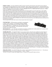
POWER AMPLIFIER – The SHUTTLE MAX 6.0 uses a state-of-the-art, Class D power amplier with a high frequency
Switch Mode Power Supply (SMPS) to achieve unprecedented high performance and lightweight packaging. Switch
Mode Power Supplies convert the AC line directly to high voltage DC, then the precision PWM (pulse width modulation)
inverter creates a new AC power signal at a frequency more than 1000 times higher than the original wall frequency of
50/60Hz. This new high voltage, high frequency power signal is then fed into a custom high frequency transformer that
steps the voltage down, a high frequency rectier and high ESR lter capacitors nish the process off by converting the
high frequency AC signal back to the DC voltages that the amplier’s internal circuitry uses. One advantage of this con-
version process is that the DC power supply rails are refreshed more than 1000 times more often than in traditional linear
supplies, thus reducing annoying hum in the audio signal. The high frequency switching is used to reduce the size and
weight of the magnetic and lter components while increasing the performance by recharging the power supply rails more
often. The Class D amplier uses digital PWM techniques similar to those in more familiar digital to analog converters to
reduce the size and weight by a factor of 10 times that of a comparably rated conventional Class AB amplier. Essentially,
a Class D amplier converts the analog signal into a logic level PWM digital signal with a digital to analog converter, level
shifts this PWM signal up to a higher voltage and current and then reconstructs the analog signal by passing it through
what is essentially a power digital to analog converter. Additionally, we developed our own, proprietary limiting and signal
processing techniques to give a distinctly analog feel and sound to the Class D platform. This system provides exceptional
performance even for low frequency applications such as bass guitar.
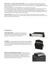
SPEAKER OUTPUTS – The SHUTTLE MAX 6.0 provides 2 parallel Speakon® connectors (wired 1+/1-). The minimum
speaker load is 4 ohms. Do not ground either the “+” or the “-” outputs.
The SHUTTLE MAX 6.0 power amp design delivers 375 watts at 8 ohms and 600 watts at 4 ohms.
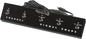
FOOTSWITCHES – A DIN connector is provided for connecting the
included 5-button footswitch. This footswitch controls CHANNEL
switching and mixing along with all the GLOBAL SIGNAL SHAPE
circuits. Additionally a ¼” footswitch jack is also provided for switch-
ing the MUTE function separately. Any single button latching style
footswitch will operate this function.