


General Information
14 312775G
General Information
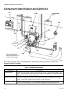
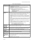
• Reference numbers and letters in parentheses in
the text refer to numbers and letters in the illustra-
tions.
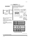
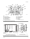
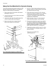
•F
IG. 2, page 10, shows the basic components of a
manual system. Contact your Graco distributor for
actual system designs.
• Be sure all accessories are adequately sized and
pressure-rated to meet system requirements.
• There must be a shutoff valve between each fluid
supply line and the ProMix system.
• A 100 mesh minimum fluid filter must be installed on
component A and B fluid supply lines.
• To protect the EasyKey screens from paints and
solvents, clear-plastic protective shields are avail-
able in packs of 10 (Part No. 197902). Clean the
screens with a dry cloth if necessary.
Wall Mounting
1. See Dimensions and Mounting Hole Layouts,
page 32.
2. Ensure that the wall and mounting hardware are
strong enough to support the weight of the equip-
ment, fluid, hoses, and stress caused during opera-
tion.
3. Using the equipment as a template, mark the
mounting holes on the wall at a convenient height
for the operator and so equipment is easily accessi-
ble for maintenance.
4. Drill mounting holes in the wall. Install anchors as
needed.
5. Bolt equipment securely.
Air Supply
Requirements
• Compressed air supply pressure: 75-100 psi
(517-700 kPa, 5.2-7 bar).
• Air hoses: use grounded hoses that are correctly
sized for your system.
• Air regulator and bleed-type shutoff valve:
include in each air line to fluid supply equipment.
Install an additional shutoff valve upstream of all air
line accessories to isolate them for servicing.
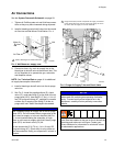
• Air line filter: a 10 micron or better air filter is rec-
ommended to filter oil and water out of the air supply
and help avoid paint contamination and clogged
solenoids. See F
IG. 2.
Trapped air can cause a pump or dispense valve to
cycle unexpectedly, which could result in serious injury
from splashing or moving parts. Use bleed-type shutoff
valves.