


Fluid Supply
18 312775G
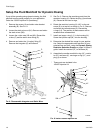
Setup the Fluid Manifold for Dynamic Dosing
If you will be operating using dynamic dosing, the fluid
manifold must be setup properly for your application.
Order the 15U955 Injection Kit (accessory).
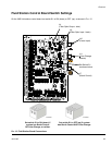
1. Remove the screws (A) and static mixer bracket
assembly (B). See F
IG. 8.
2. Loosen the static mixer nut (N1). Remove and retain
the static mixer (SM).
3. Loosen the u-tube nuts (N2 and N3). Discard the
u-tube (C) and the static mixer fitting (D).
4. Remove and retain the 1/4 npt(m) fitting (F).
Remove the integrator (G) and discard.
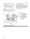
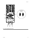
5. See F
IG. 9. Remove the remaining parts from the
restrictor housing (H). Retain the plug (J) and base
(K). Discard all the used o-rings,
6. Rotate the restrictor housing (H) 180° so the set-
screw (S) is at top left, as shown in F
IG. 9. Remove
and retain the two setscrews (S). Discard the
o-rings (L3). The position of these screws will be
reversed when reassembled.
7. Install one larger o-ring (L1*) in the housing (H).
Screw the injection cap (M*) into the housing.
8. Determine the desired flow range for your applica-
tion. Select the appropriate size restrictor for your
selected flow and ratio, using the Dynamic Dosing
Restrictor Selection Graphs on pages 34-39 as a
guide. Install the restrictor (R*) in the base (K).
9. Assemble the smaller manifold o-ring (L2*), restric-
tor (R*) and base (K), one larger o-ring (L1*), and
plug (J) as shown.
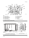
F
IG. 8. Disassemble Integrator and Static Mixer
N1
A
B
SM
C
D
TI15004a
F
G
N2
N3
F
IG. 9. Install 15U955 Injection Kit
L1*
L2*
H
K
M*
SM
J
N1
TI13360b
L1*
F
S
R*
* These parts are included in the
15U955 Injection Kit.
L3*