


Electrical
24 312775G
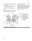
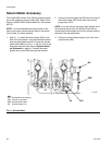
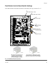
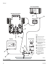
Connect Color Change Module
To install the color change module(s), see manual
312787.
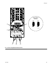
Connect a 5-pin electrical cable from the labeled con-
nection port
(J11) on the fluid station control
board to the color change board. See F
IG. 16.
If you are using two color change modules to add colors,
connect a 5-pin electrical cable from the first color
change board to the second color change board.
Set switches S3-S6 on the color change board(s) as
shown in Table 2 and F
IG. 16, depending on the number
of color change boards and color change modules being
used in your system.
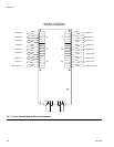
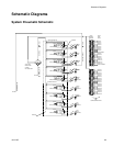
For wiring between the color change board and the sole-
noids, see the color change module electrical sche-
matic, F
IG. 17.
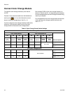
Table 2: Color Change Board Switch Settings
Two Color Change Boards
Color Change Board 1 Color Change Board 2
Effect on System
S3 S6 S5 S4 S3 S6 S5 S4
Terminatio
n
Resistor Board ID
Catalyst
On/Off
Color
On/Off
Terminatio
n
Resistor Board ID
Catalyst
On/Off
Color
On/Off
OFFONONONONOFF
NOT USED
4 catalyst valves, 30 color
valves
OFF ON OFF ON ON OFF 0 catalyst valves, 30 color
valves
One Color Change Board
ON ON ON ON
NOT PRESENT
4 catalyst valves, 12 color
valves
ON ON ON OFF 4 catalyst valves, 0 color
valves
ON ON OFF ON 0 catalyst valves, 12 color
valves