


8
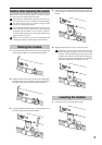
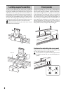
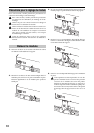
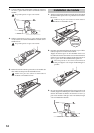
Locking support assembly
As shown in the illustration, the support arm, bracket and
latch parts fit together around the rear rail to form the lock-
ing support assembly. The raised tabs on the support arm
slide into the slots on the top of the bracket to hold every-
thing together. To attach the locking support assembly, fas-
ten the bracket to the support arm by sliding it horizon-
tally (to the left) and tightening the screw on the bracket.
To remove the locking support assembly, loosen the screw
and slide the bracket to the right to release the two pieces.
Make sure that the bracket is oriented correctly.
When performing this step, be careful not to cut your
hand on the metal parts.
Rear rail
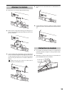
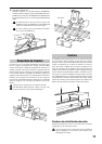
Cover panels
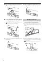
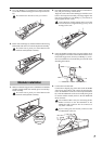
The keyboard assembly can be used with or without the these
decorative “filler” panels. The cover panels will need to be
removed when using two modules. As shown in the illus-
tration, the front edge of the cover panels are held in place
by the retaining bar. The back edge of the cover panels fit
into the channel on the top of the keyboard assembly’s rear
rail. To remove the cover panels, remove the retaining bar as
shown in step 4 of “Module removal” and lift off the cover
panels. Replace the retaining bar as described in step 2 of
“Module installation.” To replace the cover panels, remove
the retaining bar, place the back edge of the cover panels on
the top of the rear rail, and replace the retaining bar.
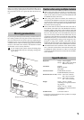
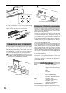
Caution when attaching the cover panel
Align the projections of the cover panel with the slot of the
rear rail, and press the cover panel into place.
If you press the cover panel when the projections are
not aligned with the slot, you may damage the pro-
jections.