120
Program operating mode
Page 17 - LFO1
(–) values will cause EG times to shorten as you play more
strongly. With a setting of 0, the EG times will be as specified
by the “Amp envelope” parameters (see page 14-118).
Attack Time Swing
This parameter specifies the direction of the effect that
“AMS1” will have on “Attack Time”. With positive (+) values
of “Intensity”, setting this parameter to + will allow AMS1 to
lengthen the time, and setting it to – will allow AMS1 to
shorten the time. With a setting of 0 there will be no effect.
Decay Time Swing
This parameter specifies the direction of the effect that
“AMS1” will have on “Decay Time”. With positive (+) values
of “Intensity”, setting this parameter to + will allow AMS1 to
lengthen the time, and setting it to – will allow AMS1 to
shorten the time. With a setting of 0 there will be no effect.
Slope Time Swing
This parameter specifies the direction of the effect that
“AMS1” will have on “Slope Time”. With positive (+) values
of “Intensity”, setting this parameter to + will allow AMS1 to
lengthen the time, and setting it to – will allow AMS1 to
shorten the time. With a setting of 0 there will be no effect.
Release Time
This parameter specifies the direction of the effect that
“AMS1” will have on “Release Time”. With positive (+) val-
ues of “Intensity”, setting this parameter to + will allow AMS1
to lengthen the time, and setting it to – will allow AMS1 to
shorten the time. With a setting of 0 there will be no effect.
AMS2 (Alternate Modulation Source 2)
This is another alternate modulation source for the Amp EG.
See above “AMS1” parameters.
PAGE 17 - LFO1
In this and the next page you can make settings for the LFO
that can be used to cyclically modulate the Pitch, Filter, and
Amp of each oscillator. There are two LFO units for each
oscillator. By setting the LFO1 or LFO2 Intensity to a negative
(–) value for Pitch, Filter, or Amp, you can invert the LFO
waveform.
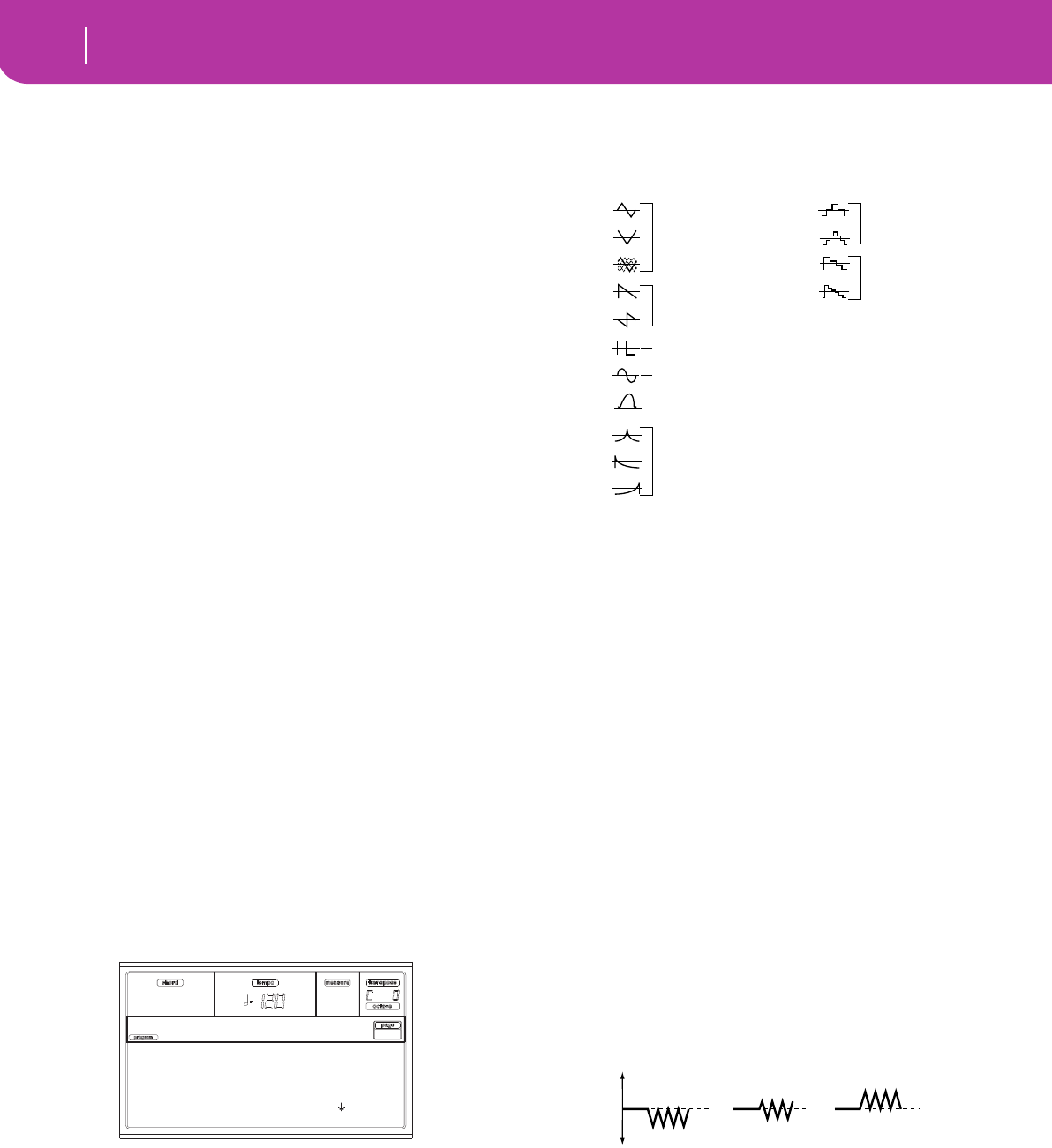
Wave
This parameter selects the LFO waveform. The numbers that
appear at the right of some of the LFO waveforms indicate
the phase at which the waveform will begin.
Frequency
Set the LFO frequency. A setting of 99 is the fastest.
00…99 Frequency rate.
Key Sync
This parameter specifies if the LFO is synchronized to key
strokes.
On The LFO will start each time you play a note,
and an independent LFO will operate for each
note.
Off The LFO effect that was started by the first-
played note will continue to be applied to each
newly-played note. (In this case, Delay and
Fade will be applied only to the LFO when it is
first started).
Offset
This parameter specifies the central value of the LFO wave-
form. For example, with a setting of 0 as shown in the follow-
ing diagram, the vibrato that is applied will be centered on
the note-on pitch. With a setting of +99, the vibrato will only
raise the pitch above the note-on pitch, in the way in which
vibrato is applied on a guitar.
When “Wave” is set to Guitar, the modulation will occur only
in the positive (+) direction even if you set “Offset” to 0.
Here are offset settings and pitch change produced by vibrato
-99…+99 Offset value.
Delay
This parameter specifies the time from note-on until the LFO
effect begins to apply. When “Key Sync” is Off, the delay will
apply only when the LFO is first started.
0…99 Delay time.
Fade In
This parameter specifies the time from when the LFO begins
to apply until it reaches the maximum amplitude. When “Key
Sync.” is Off, the fade will apply only when the LFO is first
started.
Selected: Osc1
Wave: Triangle Rand
Frequency: 31
Key Sync: On
LFO1 |Osc1
Triangle wave
Phase will change
randomly at each key-in
Sawtooth down
↓
Square wave
Sine wave
Guitar vibrato
Triangle 0
Triangle 90
Triangle
Random
Saw 0
Saw 180
Square
Sine
Guitar
Exponential
Triangle
Exponential
Saw Down
Exponential
Saw Up
Step Triangle – 4
Step Triangle – 6
Step Saw – 4
Step Saw – 6
Random1 (S/H):
Conventional sample & hold (S/H) in which the
level changes randomly at fixed intervals of
time
Random2 (S/H):
Both the levels and the time intervals will
change randomly.
Random3 (S/H):
The maximum level and minimum level will
alternate at random intervals of time (i.e., a
square wave with random period).
Random4 (Vector)
Random5 (Vector)
Random6 (Vector)
These types cause Random 1–3 to change
smoothly. They can be used to simulate the
instability of acoustic instruments etc.
offset = –99 offset = 0 offset = +99Pitch
Pitch at note-on


