


10
ONYX 1620
ONYX 1620
Onyx 1620 Features
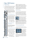
Channel Strips
There are two kinds of channel strips on the Onyx 1620:
Mono and Stereo. The mono channel strips (channels
1-8) have mic and line input connectors. In addition,
channels 1 and 2 have high-impedance instrument
inputs so you can connect a guitar directly to the mixer.
The stereo channel strips (channels 9-16), have
two line input connectors per channel strip, left and
right. The stereo path is maintained
throughout the channel strip, sharing
the channel’s controls (the controls
work on both left and right signals at
the same time).
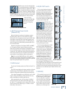
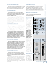
1. MIC Input (Channels 1-8)
This is a female XLR connector, which
accepts a balanced microphone input
from almost any type of microphone.
The microphone preamps feature our
new Onyx design, with higher fi delity
and headroom rivaling any standalone
mic preamp on the market today.
The XLR inputs are wired as follows:
Pin 1 = Shield or ground
Pin 2 = Positive (+ or hot)
Pin 3 = Negative (– or cold)
2. HI-Z Instrument Input
(Channels 1-2)
This is a 1/4" connector, which ac-
cepts an unbalanced instrument-level
input signal from a high-impedance
instrument like a guitar.
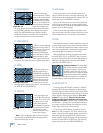
3. LINE Input (Channels 3-16)
This is a 1/4" TRS connector, which ac-
cepts a balanced or unbalanced line-level
input signal from almost any source.
When connecting a balanced signal to
the LINE inputs, wire them as follows:
Tip = Positive (+ or hot)
Ring = Negative (– or cold)
Sleeve = Shield or ground
When connecting an unbalanced
signal, wire them as follows:
Tip = Positive (+ or hot)
Sleeve = Shield or ground
Note: For the stereo channels 9-16, if a signal is
plugged into the LEFT (MONO) side and nothing is
plugged into the RIGHT side, the signal is automatically
connected to both LEFT and RIGHT sides. This is called
jack normalling. As soon as something is plugged into
the RIGHT side, the normalled connection is broken
and the LEFT and RIGHT inputs become stereo inputs
(LEFT goes to the LEFT MAIN OUT and RIGHT goes to
the RIGHT MAIN OUT).
4. MIC/HI-Z Switch
Channels 1 and 2 have an extra button for switching
between the MIC and HI-Z inputs. When the button
is out (MIC), the XLR MIC input is used and the HI-Z
input is disconnected. When the button is pushed in
(HI-Z), the 1/4" HI-Z input is used and the XLR MIC in-
put is disconnected. The input stage of the HI-Z inputs
is specially designed for the high-impedance pickups on
guitars.
Plugging a guitar into a lower-impedance
line input (like those on channels
3-16)
can result in the loss of high
frequencies, causing an unnatural and
dull sound.
Normally, you must use
a direct box between a guitar and a
mixer’s input, which serves to convert the impedance of
the guitar from high to low. The HI-Z inputs on chan-
nels 1 and 2 make the need for a direct box unnecessary.
HOWEVER: The HI-Z inputs are unbalanced, so if you’re
doing a live show and running a long cord between the
instrument and the mixer (say over 25 or 30 feet), it is
best to use a direct box with a balanced output to avoid
picking up noise over the length of the cord.
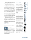
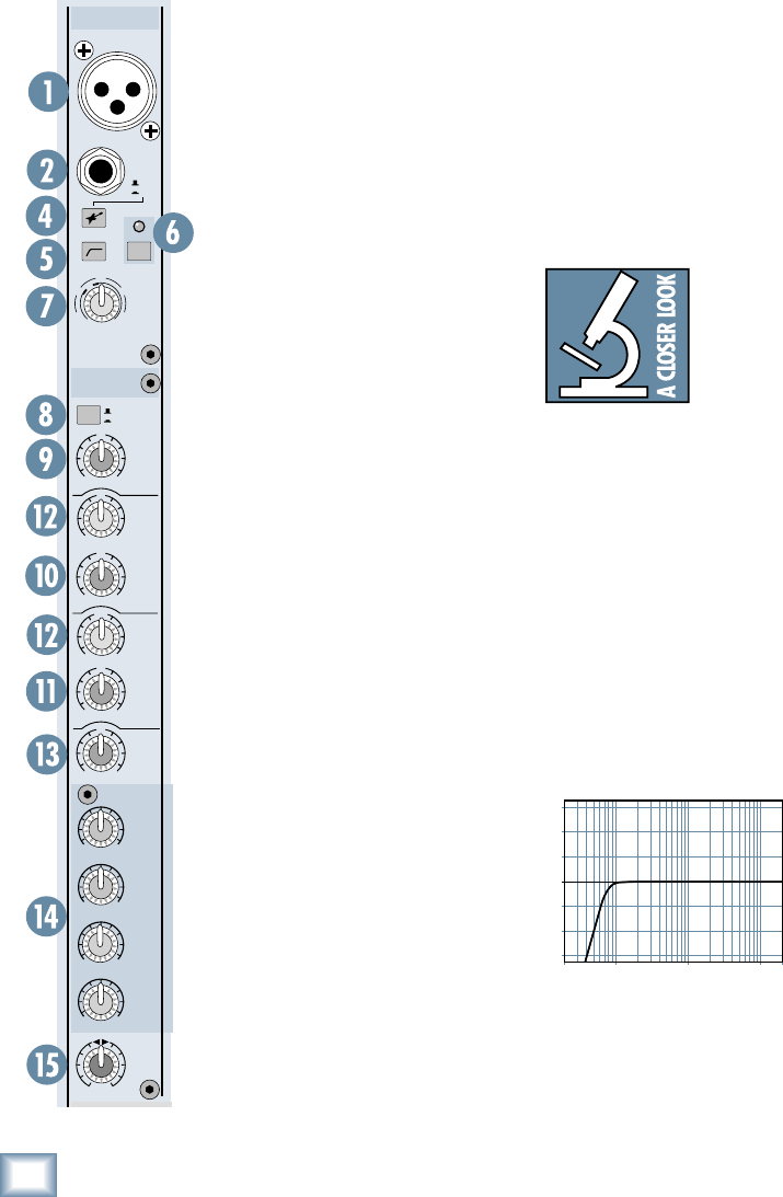
5. Low-Cut Switch (Channels 1-8)
The Low-Cut switch, often referred to as a high-pass
fi lter, cuts bass frequencies below 75 Hz at a rate of 18 dB
per octave.
We recommend that
you use the Low-Cut fi lter
on every microphone
application except kick
drum, bass guitar, bassy
synth patches, or record-
ings of earthquakes.
These aside, there isn’t
much down there that
you want to hear, and fi ltering it out makes the low stuff
you do want much more crisp and tasty. Not only that,
but the Low-Cut fi lter can help reduce the possibility of
feedback in live situations and it helps to conserve the
amplifi er power.
20
Hz
100
Hz
1k
Hz
10k
Hz
20k
H
z
–15
–10
–5
0
+5
+10
+15
Low Cut
Mono Channel
1
X
D
R
M
I
C
P
R
E
GAIN
+40dB
U
-20dB
U
20
30
40
60
FREQ
HIGH
12kHz
LOW
MID
HIGH
MID
U
+15
-
15
U
+15
-
15
U
+15
-
15
U
+15
-
15
LOW
80Hz
FREQ
EQ
AUX
4
3
2
1
PAN
OUT
IN
OO
MAX
OO
MAX
OO
MAX
OO
MAX
LR
2k
8k400
400
2k100
HI
-
Z
1
HI
-
Z
MIC
48V48V