


17
Owner’s Manual
Owner’s Manual
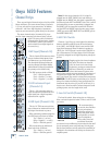
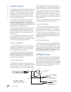
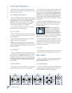
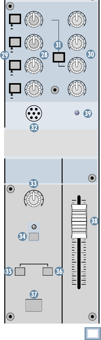
32. Internal TALKBACK MIC
This is where the built-in talkback microphone is located.
This is an omni-directional dynamic microphone, so it will
pick up your voice from anywhere in front of the mixer.
33. TALKBACK LEVEL
Use this knob to control the level of the talkback
signal being routed to the PHONES or AUX 1-2 outputs.
This controls the talkback level for either the internal
or external TALKBACK MICs.
You should start with the TALKBACK LEVEL control
turned down, and then slowly turn it up until you get
confi rmation from whoever is listening to headphones
or monitors that they can hear you. Once you have set
the level, you can leave it there for the duration of the
session (or the gig).
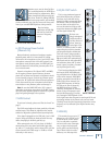
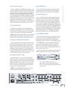
34. EXTERNAL MIC Switch
If you are in a noisy environment, the built-in talkback
mic may not work as well because it picks up the ambi-
ent noise as well as your voice. You will probably have
better results if you use an external microphone that
you can talk directly into.
If you are using an external mic, you must push in
the EXTERNAL MIC switch. The indicating LED lets
you know when the switch is pushed. When the switch
is out, the built-in TALKBACK MIC is used, regardless
of whether or not you have an external mic plugged in.
When the switch is pushed in, the built-in mic is discon-
nected and only the external mic is used.
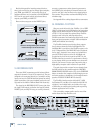
35. TALKBACK to PHONES
Push in the CR/PHONES switch to route the talkback
signal to the PHONES (24) output. Use this to commu-
nicate with the talent in the
studio through the head-
phones during a recording session.
When the talkback
circuit is activated (by pushing the TALKBACK (37)
switch) and the CR/PHONES switch is in, the CONTROL
ROOM outputs are attenuated by 20 dB to allow the
engineer’s voice to come through loud and clear.
36. TALKBACK to AUX 1-2
This switch routes the talkback signal to the AUX 1
and 2 outputs (50). Use this to communicate with the
musicians on-stage through their monitors during a live
performance.
By the way, it is okay to have both destination switch-
es pushed in at the same time. The talkback signal will
be routed to both destinations. But if you don’t have ei-
ther of the destination switches pushed in, the talkback
signal won’t go anywhere. You might as well be talking to
a brick wall.
37. TALKBACK Switch
This is a momentary switch, meaning it’s only active
when you hold the switch down. As long as you hold
this switch down, the talkback signal is routed to the
outputs determined by the destination switches (35/36).
Release the switch, and the talkback circuit is turned off.
MAIN MIX and POWER LED
These are a few more important features that
shouldn’t be overlooked.
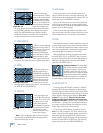
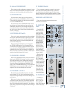
38. MAIN MIX
Fader
The MAIN MIX
fader controls the
output level just
before the MAIN
OUTPUTS (1/4" and
XLR) (42/48) and
the TAPE OUTPUTS
(43). When MAIN
MIX is selected
for the CONTROL
ROOM/PHONES
SOURCE (20), the
MAIN MIX fader
(38) also controls
the main mix level
in the CONTROL
ROOM and PHONES
outputs (40/24).
When the fader
is fully down, the
MAIN MIX is off.
The “U” marking
indicates unity gain,
and fully up provides
10 dB of additional
gain. Typically, this
fader is set near the
“U” label and left
alone, but it can
be used for song
fade-outs or quick
system-wide mutes.
39.
POWER LED
This LED per-
forms one func-
tion—it lets you
know when the
Onyx 1620 is turned
on and ready to go!
MAIN
MIX
AUX MASTERS AUX RETURNS
4
3
2
1
4
3
2
1
FX
TO
MON
TALKBACK
PRE
POST
PRE
POST
PRE
POST
PRE
POST
TALK
BACK
MIC
POWER
OO
+15
OO
+10
OO
+15
OO
+10
OO
+15
OO
+10
OO
+15
OO
+10
AUX
1-2
CR/
PHONES
DESTINATION
EXTERNAL
MIC
TALKBACK
dB
30
20
10
40
50
5
5
U
60
10
OO
LEVEL
OO
MAX