


22
Compact Mixer Reference Guide
MIXER ANATOMY: CHAPTER 2
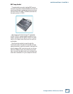
Bus/Subgroup Outputs
In 4- and 8-Bus consoles, the output
of the PAN control can be assigned to
subgroup busses. The ASSIGN switches
(1-2, 3-4, L-R) direct the channel out-
put to pairs of busses. The subgroup bus
outputs appear on the balanced 1/4"
TRS SUB OUT jacks.
The subgroup outputs can be used
to feed a mix of several channels (for
example six mics on a drum kit) to a
single pair of recorder tracks.
Bus Output Levels
The subgroup bus output level on all
of the Mackie mixers is nominally 0 dBu. The output
level of the busses is controlled by the bus faders.
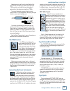
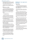
On the 8-Bus console, the bus output level is
switch-selectable between +4 dBu and –10 dBV, al-
lowing you to properly match pro or semi-pro record-
ers.
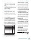
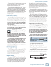
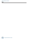
Double (and triple) Bussing
The bus outputs on the 1642-VLZ PRO,
SR, and 8-Bus mixers have duplicate
jacks to make connection to a multitrack
recorder easier. Even though the SR and 1642 are
four-bus mixers with four subgroups, they have eight
SUB OUT jacks for feeding eight recorder tracks,
thanks to a trick called Double Bussing.
SUB OUTS 1 and 5 carry the same signal, as do 2
and 6, 3 and 7, and 4 and 8. By connecting those eight
jacks to the eight inputs of your recorder, you can
route any input channel to any track.
To record onto Track 1, assign the input channel to
Bus 1 by pressing the 1-2 ASSIGN button and turning
the PAN control fully left. On the recorder, put Track
1 into the Record mode, being sure that Track 5 is in
the Safe or Play mode. To record on Track 5, use the
same bus assignment on the mixer, but put Track 5 in
Record. To record on Track 2 or 6, ASSIGN to 1-2 and
pan fully right.
The 8-Bus console extends this trick by tripling the
outputs of each of the eight busses to accommodate a
24-track recorder.
On most Mackie mixers, subgroup busses can be
routed to the main outputs so that all channels as-
signed to that subgroup can be controlled by a single
fader, retaining the balance and pan position set by
the channel controls. You can individually mic each
of the background singers, assign their channels
to a single subgroup or pair, and use the subgroup
fader(s) to bring the background vocals up in the
mix when they’re needed.
Not all models have the same SUB outputs, level
controls, and routing capabilities. Input channels on
the CFX series cannot be routed directly to the MAIN
outputs, but must fi rst be routed to a pair of sub-
group busses, which are in turn assigned to the MAIN
outputs by switches in the mixer’s Subgroup section.
The PPM series has no SUB outputs since it has no
subgroups.
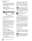
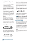
ALT 3-4 Outputs
The dual-purpose MUTE/ALT 3-4 switch on the
1202/1402-VLZ PRO and Onyx 1220/1620 mixers is
a variation on the subgroup concept. When Greg
Mackie was designing our fi rst compact mixer, he
wanted to include a mute switch for each channel.
Mute switches do just what they say — turn off the
signal by sending it into oblivion. “Gee, what a waste,”
Greg reasoned. “Why not have the mute button route
the signal somewhere else useful - like an alternate
stereo bus?”
So MUTE/ALT 3-4 really serves two purposes: mut-
ing (handy during a mixdown session or live show)
and signal routing. For multitrack recording and live
mixing, it serves as an extra stereo bus.
One difference between the ALT 3-4 outputs and
BUS OUTs 3 and 4 on the larger consoles is that
there’s no output level control for those busses
– they run at unity gain. Another difference is that
it’s either/or routing – a channel can’t be assigned to
both the MAIN and ALT outputs simultaneously. But
like the true 4-bus consoles, the ALT busses can be
routed to the MAIN outputs, serving as a submaster
pair.
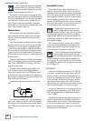
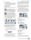
To MUTE channels in the main mix, leave the ALT
3-4 outputs disconnected. Pressing the MUTE/ALT
3-4 button switches the channel signal from the
MAIN to the ALT 3-4 busses, sending it off to never-
never land, disconnecting it from the MAIN MIX, and
PAN
SOLO
L - R
3
–
4
1
–
2
OL
-
20
1
MUTE
L
R
OO
SUBMASTER / TAPE OUTPUTS
+4dBu BALANCED / –10dBV UNBALANCED
6
14
5
13
4
12
3
11
OUT +4dBu
IN –10dBV
20 192122
OPERATING
LEVEL