28
MODIFICATIONS
CR1604-VLZ Post-EQ Mod
This changes
AUX SENDS 1
and
2
, with the
pre switch engaged, to receive their signals post-
EQ
instead of pre-
EQ
. The signal remains post-low cut,
pre-mute and pre-fader. With the pre switch disen-
gaged (up), the signals are not affected by the mod.
The following must be performed for each channel
you wish to modify:
1. Remove all cords, including the power cable,
from the CR1604-VLZ.
2. Place the mixer upside-down on a dry, non-
marring surface.
3. If you have converted your mixer to the rack-
mount position or have installed a RotoPod,
undo those changes and temporarily configure
the mixer in the original desktop mode. You do
not have to install the pod, just get it out of the
way of the bottom cover.
4. Remove the screws that attach the bottom
cover. Keep track of what screws go where.
Remove the bottom cover.
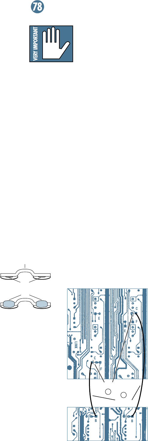
5. Cut the conductor at point C, between the
square and round pads. Be careful to cut all
the way through the conductor, and do no cut
any nearby traces. Each channel is slightly
different, but this graphic shows Channel 16,
which is very different from the others, and
Channel 15 (respectively), which is similiar to
the remaining channels.
6. Add a jumper from the square pad at point B
to the square pad at point C.
7. Repeat for each channel you wish to modify.
8. Check your work very carefully, them put the
bottom cover back the way you found it.
You’re done!
UL Warning
CAUTION! These modi-
fication instructions are
for use by qualified per-
sonnel only. To avoid
electric shock, do not perform any servicing
other than changing the fuse unless you
are qualified to do so. Refer all servicing
and modifying to qualified personnel.
Mackie Disclaimer
Any modification of any Mackie Designs prod-
uct must be performed by a competent electronic
technician. Mackie Designs accepts no responsi-
bility for any damages or injuries caused by any
modification, regardless of the source of the modi-
fication instructions or the qualifications of the
technician performing them. In the case of such
damages, Mackie Designs may declare warranty
privileges void. BE CAREFUL!
About Jumpers
We recommend solid (non-stranded) wire,
26–28 gauge (wire-wrapping variety). When in-
stalling jumpers, do not run their ends through
holes in the circuit board. Rather, solder them flat
against the desired pad (the flat silver area, possi-
bly with a hole in the middle). Make sure the ends
of these flat wires do not extend beyond the pad.
6
5
jumpers
here
cut
here
Holes
Jumper
Solder
BEFORE
AFTER
Ch. 16 Ch. 15


