


17
Owner’s Manual
Owner’s Manual
0dB=0dBu
20
10
7
4
2
0
2
4
7
10
20
30
20
10
7
4
2
0
2
4
7
10
20
30
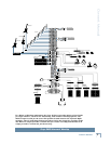
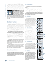
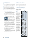
LSOLO R
CLIP
RUDE
SOLO
PFL AFL
+15V -15V +48V +12V
POWER
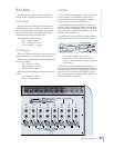
45. AFL Solo Switch
The AFL switch allows you to hear the Group signal
through your headphones or monitor outputs. This
comes after the Group Fader and before the MUTE
switch, so you can hear the relative signal level on each
Group even when they are muted.
When you engage the AFL switch on two consecutive
odd/even Groups (i.e., 1 and 2, 3 and 4, etc.), the soloed
signal appears in stereo in the headphones and moni-
tor outputs. This is useful when you are using a pair
of Group Sends in stereo to feed an in-ear monitoring
system.
Remember, PFL solo mode always overides AFL solo
mode. If you engage a PFL solo switch on a mono or
stereo channel, the AFL solo is disconnected from the
headphones and monitor outputs and replaced with the
PFL signal. The Rude Solo LEDS below the SOLO meters
indicate which solo mode is active.
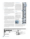
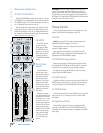
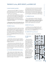
46. GROUP/AUX FLIP Switch
This switch “fl ips” the controls for the Aux Sends and
the Group Sends, so that the Group Faders control the
Aux Send levels, and the Aux Send GAIN controls adjust
the Group levels. The Group signals still appear at the
GROUP SEND outputs and the Aux Send signals still
appear at the AUX SEND outputs.
This allows you to use the long-throw (100 mm)
Group Fader to make more precise settings for the Aux
Sends, if required.
The following chart shows what happens to each
control in the Aux Send and Group sections when the
GROUP/AUX FLIP Switch is pushed in:
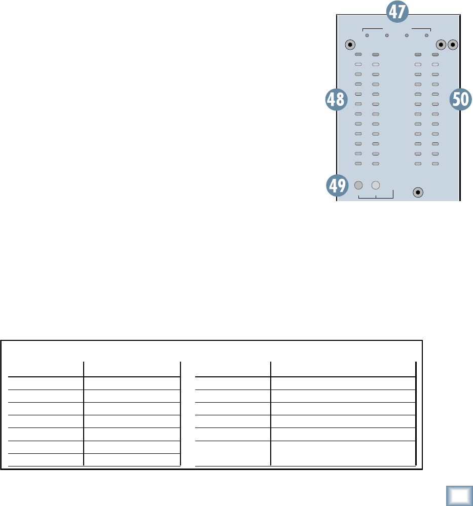
Metering, Matrix, and Power
LEDs
47. POWER Indicators
These four LEDs indicate the status of the internal
power supply voltages. The +15V and –15V supplies
power the audio circuits, the +48V is the phantom
power applied to the XLR MIC inputs (when the 48V
switch is pushed in on the channel strips), and the –12V
supply powers some internal relay circuits and the lamp
connectors.
When all four LEDs are lit, you know that the internal
power supply (or the external redundant power supply,
if connected) is operating correctly.
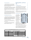
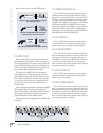
48. SOLO Meters
The Onyx SOLO
meters are made up of
two columns of twelve
LEDs, with three
colors to indicate dif-
ferent ranges of signal
level, traffi c light
style. They range from
–30 at the bottom, to 0
in the middle, to +20
(CLIP) at the top.
If there are no
channels in SOLO, the
meters won’t do any-
thing. When a channel is soloed, the meters refl ect the
program level of the selected source prior to the SOLO,
MONITOR, and PHONES [61/63/64] level knobs.
When a mono channel (or channels) is soloed, only the
left meter indicates signal, confi rming the monophonic
status of the soloed signal. When a stereo Aux Input is
soloed, or stereo AFL solo mode is selected, both meters
indicate the corresponding left and right signals.
Aux Send MUTE Mutes Group Signal
Aux Send GAIN Adjusts Group Signal
Aux Send AFL Solos Group Signal
Aux Send Control
With GROUP/AUX FLIP Switch Down
Function Group Control Function
Group MUTE Mutes Aux Send Signal
Group Fader Adjusts Aux Send Signal
Group AFL Solos Aux Send Signal
Signal Level LEDs Indicates Aux Send Signal Level
Main Mix Switch Routes Group Signal to Main Mix
Group PAN Adjusts amount of Group Signal
to left and right Main Mix