


18
ONYX 80 SERIES
ONYX 80 SERIES
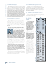
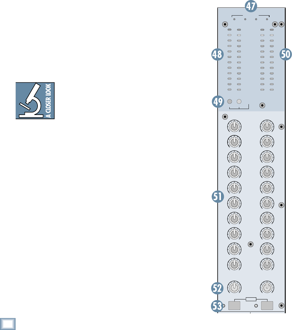
49. RUDE SOLO Lights
These LEDs fl ash on and off when a channel’s solo is
active, as an additional reminder beyond the indicating
LEDs next to each PFL or AFL button. The green LED
indicates PFL solo mode, and the amber LED indicates
AFL solo mode. If you work on a mixer that has a solo
function with no indicator lights and you happen to
forget you’re in solo mode, you can easily be tricked
into thinking that something is wrong with your mixer.
Hence, the RUDE SOLO lights. It’s especially handy at
about 3 am when no sound is coming out of your moni-
tors but your multitrack is playing back like mad.
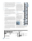
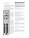
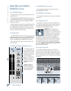
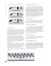
50. LEFT/RIGHT Level Meters
Like the SOLO meters, the Onyx 80 Series Left and
Right Level meters are made up of two columns of
twelve LEDs, with three colors to indicate different
ranges of signal level, traffi c light style. They range from
–30 at the bottom, to 0 in the middle, to +20 (CLIP) at
the top.
The 0 LED in the middle is labeled 0 dB = 0 dBu.
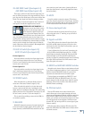
You may already be an expert at the
world of “+4” (+4 dBu=1.23 V) and
“–10” (–10 dBV=0.32 V) operating
levels. What makes a mixer one or
the other is the relative 0 dB VU (or
0 VU) chosen for the meters. A “+4”
mixer, with +4 dBu pouring out the back will actually
read 0 VU on its meters. A “–10” mixer, with a –10 dBV
signal trickling out will read, you guessed it, 0 VU on its
meters. So when is 0 VU actually 0 dBu? Right now!
Mackie mixers show things as they really are. When 0
dBu (0.775 V) is at the outputs, it shows as 0 dB VU on
the meters. What could be easier? By the way, the most
wonderful thing about standards is that there are so
many to choose from.
Thanks to the Onyx 80 Series’ wide dynamic range,
you can get a good mix with peaks fl ashing anywhere
between –20 and +10 dB on the meters. Most amplifi ers
clip at about +10 dBu, and some recorders aren’t so
forgiving either. For best real-world results, try to keep
your peaks between “0” and “+7.”
Remember, audio meters are just tools to help assure
you that your levels are “in the ballpark.” You don’t have
to stare at them (unless you want to).
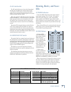
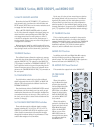
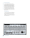
51. MATRIX A and B Input Controls
The Matrix A and B controls allow you to create
separate mixes, or a stereo mix, from Groups 1 through
8 and the Left and Right Mix outputs. Simply adjust
the 10 input controls to create the mix you want at the
MATRIX A or B outputs.
52. MATRIX A and B MASTER Controls
Use these controls to adjust the overall signal level at
the MATRIX A and B outputs.
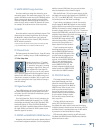
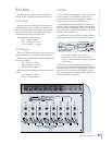
53. AFL Solo
Switch
The AFL switch allows
you to hear the Matrix
signal through your
headphones or moni-
tor outputs. This comes
after the MATRIX MAS-
TER, so you can hear the
relative signal level of
each Matrix output.
When you engage the
AFL switch on both MA-
TRIX A and B, the soloed
signal appears in stereo
in the headphones and
monitor outputs. This is
useful when you want to
use both Matrix outputs
to create a stereo mix.
Remember, PFL solo
mode always overides
AFL solo mode. If you
engage a PFL solo switch
on a mono or stereo
channel, the AFL solo is
disconnected from the
headphones and moni-
tor outputs and replaced
with the PFL signal. The
Rude Solo LEDS below
the SOLO meters indi-
cate which solo mode is
active.
0dB=0dBu
MATRIX
AB
AB
20
10
7
4
2
0
2
4
7
10
20
30
20
10
7
4
2
0
2
4
7
10
20
30
LSOLO R
CLIP
RUDE
SOLO
PFL AFL
GROUP
1
MATRIX
MASTER
LEFT
RIGHT
GROUP
2
GROUP
3
GROUP
4
GROUP
5
GROUP
6
GROUP
7
GROUP
8
+15V -15V +48V +12V
OO
+15
OO
+15
OO
MAX
OO
MAX
OO
MAX
OO
MAX
OO
MAX
OO
MAX
OO
MAX
OO
MAX
OO
MAX
OO
MAX
OO
MAX
OO
MAX
OO
MAX
OO
MAX
OO
MAX
OO
MAX
OO
MAX
OO
MAX
OO
MAX
OO
MAX
STEREO
AFLAFL
POWER