


19
Owner’s Manual
Owner’s Manual
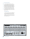
TALKBACK Section, MUTE GROUPS, and MONO OUT
By the way, it is okay to have more than one destina-
tion switch pushed in at the same time. The talkback
signal will be routed to all the destinations you have
selected. But if you don’t have any of the destination
switches pushed in, the talkback signal won’t go to any
internal destination (it appears at the TALKBACK OUT
jack [77] regardless of the destination switch settings).
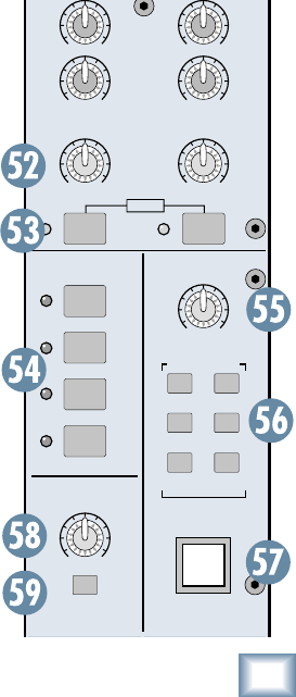
57. TALKBACK Switch
This is a latching switch, meaning it’s always active
when the switch is pushed in. As long as the switch is
engaged, the talkback signal is routed to the TALKBACK
OUT jack [77] and to the outputs determined by the
destination switches [56].
Push the switch again to
release it, and the talkback circuit is turned off.
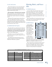
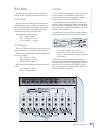
MONO OUT Section
In addition to the Left and Right Main Mix outputs,
the Onyx 80 Series provides an independent mono-
phonic output. The Left and Right Main Mix signals are
summed and sent to the MONO OUT [78].
58. MONO OUT Level Control
This controls the output level at the MONO OUT.
59. PRE FADER
Switch
When this switch is
up, the Mono Out signal
contains the summed
Left and Right Main Mix
signal after the MAIN
MIX faders, so the Mono
Output is controlled by
both the MAIN MIX fad-
ers and the MONO OUT
level control.
When this switch is
pushed in, the Mono Out
signal sums the Left and
Right Main Mix signal
before the MAIN MIX
faders, so even if the
MAIN MIX faders are
turned all the way down,
you still get a signal at
the MONO OUT.
AB
MATRIX
MASTER
DESTINATION
TALKBACK
AUX
3-4
AUX
5-6
AUX
7-8
AUX
1-2
TALKBACK
GRPS
1-8
MAIN
L/R
MUTE GROUPS
MASTER
PRE
FADER
1
2
3
4
MONO
OUT
LEVEL
LEFT
RIGHT
OO
+15
OO
+15
OO
MAX
OO
MAX
OO
MAX
OO
MAX
OO
MAX
OO
MAX
STEREO
MUTE
MUTE
MUTE
MUTE
AFLAFL
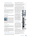
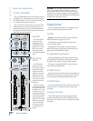
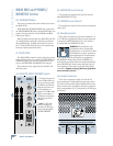
54. MUTE GROUPS MASTER
Remember the four MUTE GROUP [17] switches in
each channel strip, just above the channel fader and
MUTE switch? Well, these are the master switches used
to engage the four mute groups.
When a MUTE GROUP MASTER switch is pushed
in, all of the channels assigned to that mute group are
muted and their corresponding mute LEDs light. You
can engage more than one mute group at a time. If
a channel is assigned to two or more mute groups, it
remains muted as long as any one of the mute groups it
is assigned to is activated.
Mute groups are handy for quickly turning off a num-
ber of microphones all at once; for example, all the vocal
mics during a break, or all the drum mics...just for fun.
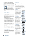
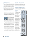
TALKBACK Section
The talkback feature allows the engineer to commu-
nicate with the talent either through the AUX 1-8 [72]
outputs, GROUPS 1-8 [74] outputs, or the MAIN L/R
[79] outputs. In addition, a TALKBACK LINE OUT [77]
jack is provided on the rear panel for patching into an
external intercom system. Connect an external micro-
phone to the TALKBACK MIC IN XLR [76] connector on
the rear panel.
55. TALKBACK LEVEL
Use this knob to control the level of the talkback
signal being routed to the AUX, GROUP, or MAIN L/R
outputs. This also controls the talkback level for the
TALKBACK LINE OUT.
You should start with the TALKBACK LEVEL control
turned down, and then slowly turn it up until you get
confi rmation from whoever is listening to headphones
or monitors that they can hear you. Once you have set
the level, you can leave it there for the duration of the
session (or the gig).
56. TALKBACK DESTINATION Switches
These switches route the talkback signal to various
outputs, including AUX 1-2, AUX 3-4, AUX 5-6, AUX 7-8,
GROUPS 1-8, and MAIN L/R OUTS. You might use a pair
of Aux Sends to communicate with musicians on-stage
through their monitors during a live performance. These
could be fl oor wedges or in-ear monitors.