


13
Owner’s Manual
Owner’s Manual
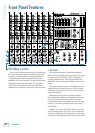
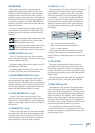
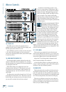
12. INSERT (CH. 1 to 6)
These unbalanced 1/4" jacks on channels 1 to 6 are for
connecting serial effects processors such as compres-
sors, equalizers, de-essers, or filters. The insert point
is after the gain switch [32] and compressor circuits
(on channels 1 – 4), but before the channel’s EQ and
level [31] controls. The channel signal can go out of
the insert jack to an external device, be processed (or
whatever) and come back in on the same insert jack.
To do this requires a special insert cable that must be
wired thusly:
Tip = send (output to effects device)
Ring = return (input from effects device)
Sleeve = common ground
Insert jacks can be used as channel direct outputs;
post-gain, and pre-EQ. See the connector section on
page 26 (figure G) showing three ways to use insert con-
nections.
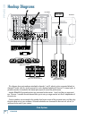
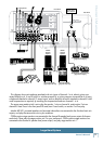
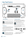
13. TAPE OUTPUTS
These stereo unbalanced RCA outputs allow you
to record the main stereo mix onto a tape deck, hard
disk recorder, automatic CD burner, or a computer, for
example. This allows you to make a recording for poster-
ity/archive/legal purposes whenever the band gets back
together again.
The tape output is the stereo main mix, not affected
by the main level [38], or the main graphic EQ [36].
14. BREAK SWITCH and LED
This important "take-a-break" switch quickly mutes
all the microphones and the mono channel line-level
inputs when the band is between sets. This will prevent
protestors or rogue karaoke singers from storming the
stage at the interval. The monitor 1 and FX/monitor 2
outputs, and the drive signal to the internal effects are
also muted. The LED will come on, as a reminder that
the break switch is engaged. Check this LED first, if you
are having trouble with no sound in your system.
You can still play the stereo channel line inputs
[10] and RCA inputs [11] in the main stereo mix. For
example, you could play a soothing CD to restore order
before the police arrive.
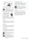
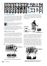
PHANTOM POWER
Most modern professional condenser mics are
equipped for phantom power, which lets the mixer
send low-current DC voltage to the mic’s electronics
through the same wires that carry audio. (Semi-pro
condenser mics often have batteries to accomplish the
same thing.) “Phantom” owes its name to an ability to
be “unseen” by dynamic mics (Shure SM57/SM58, for
instance), which don’t need external power and aren’t
affected by it anyway.
The mixer's phantom power is globally controlled
by the phantom [46] switch on the front panel. (The
phantom power for all channels is turned on and off
together.)
Never plug single-ended (unbalanced) micro-
phones, or ribbon mics into the mic input
jacks if phantom power is on.
Do not plug instrument outputs into the mic
XLR input jacks with phantom power on,
unless you know for certain it is safe to do so.
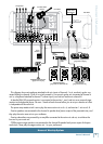
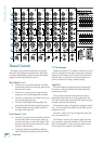
8. MONO LINE INPUTS (CH. 1 to 4)
These 1/4" jacks share circuitry (but not phantom
power) with the mic preamps, and can be driven by bal-
anced or unbalanced sources.
To connect balanced lines to these inputs, use a 1⁄4"
Tip-Ring-Sleeve (TRS) plug.
To connect unbalanced lines to these inputs, use a
1⁄4" mono (TS) phone plug or instrument cable.
9. LINE/INSTRUMENT INPUTS (CH. 5 and 6)
The line-level inputs for channels 5 and 6 can also
accept instrument-level signals if the hi-z switches
[34] are pressed in. This allows you to connect guitars
directly to channels 5 and 6, without the need for a DI
box. The input impedance is optimized for direct con-
nection, and high-frequency fidelity is assured.
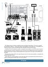
10. STEREO LINE INPUTS (CH. 7 and 8)
Channel 7 and 8 have stereo line inputs. If you
just have a mono source, plug it into the left input of
channel 7 or 8 (labeled left/mono), and the signal will
appear (as if by magic) equally on the left and right of
the main mix.
11. RCA INPUTS (CH. 7 and 8)
Channel 7 and 8 also have RCA line inputs, suitable
for connecting the line-level, unbalanced output from
CD players, tape decks, iPod docks etc. They are not
suitable for direct connection of phono-level outputs
from turntables, as a phono preamp is required.
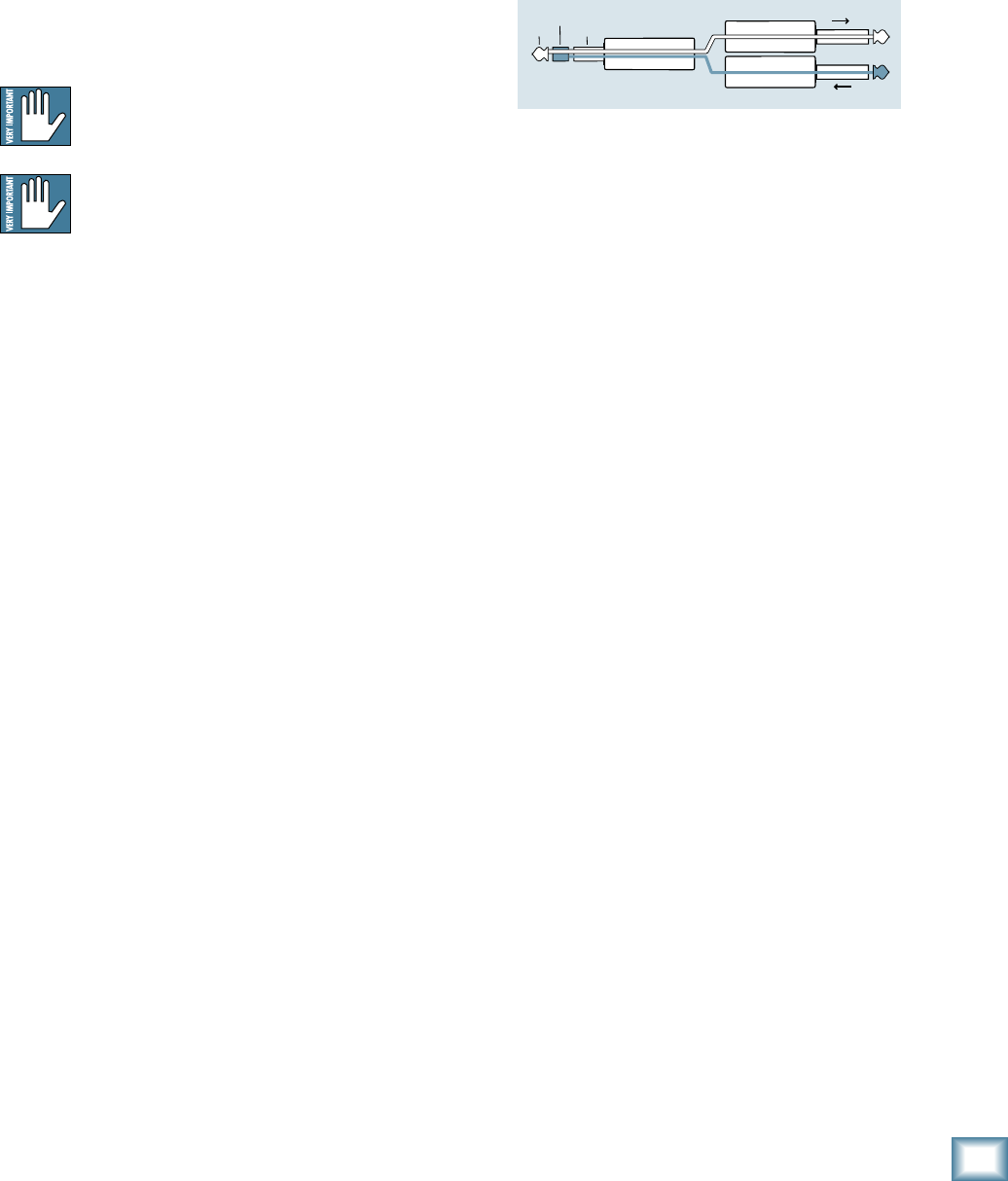
“tip”
This plug connects to one of the
mixer’s Channel Insert jacks.
“ring”
tip
ring
sleeve
SEND to processor
RETURN from processor
(TRS plug)