


SP2400 – 11
in stereo. The answer to this question will also
affect the location of the speakers in the room and
the settings for the
STEREO/MONO
switches for
the input sources.
3.
How many program sources are going to be
used?
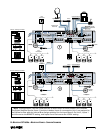
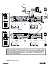
If the number of program sources is four or
less, they can be centralized at one SP2400 and
distributed via the Expansion Bus. If there are more
than four program sources, they must be
distributed among the SP2400s. Determine the
number and location of the program sources that
are going to be used.
Determine which program sources are going to
be used for each zone, and set the
LOCAL/REMOTE
and internal
BUS ASSIGN
switches appropriately.
CAUTION: Never assign more than one
program source to the same channel on
the Expansion Bus.
If there is a requirement for music-on-hold, use
Input 1 for the continuous music source (i.e.,
satellite feed, prerecorded background music, multi-
disc CD player). Then use the
DIRECT OUTPUT
jacks to route the signal to the telephone system.
If there is a jukebox, use Input 4 in Program
Priority mode (set the
AMP ADDRESS
switch #7 UP
to activate). When a signal appears at Input 4 it
overrides the selected Input source.
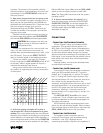
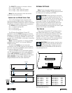
Using a chart similar to the one below can be
very helpful in organizing the various components
of the system:
Zone
Source
SAT
CD
Cassette
Tuner
Jukebox
AXXXXX
XXXXX
XX X
XX X
XXX
XXX X
XX X
B
C
D
E
F
G
4.
Is there a paging microphone? Is there a
requirement for a local microphone for a guest
speaker?
You must decide where the microphones
are going to be located. Avoid placing a microphone
near a speaker, to increase gain before feedback. If
the mics require phantom power, set the
PHANTOM
power switches to the down position for the Paging
Mic and Mic/Line Inputs. Make sure the
GAIN +40dB
switch is set to the down position as well (+40).
Note: The Paging Mic has priority over the system,
including Input 4.
5.
Is there a manual switch for paging?
Up to
three switches can be connected to the SP2400
PAGING MIC CONTROL
to manually engage the
paging microphone. Otherwise, the paging mic is
voice-activated. Adjust the
VOX
control as
described on page 19.
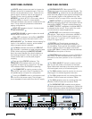
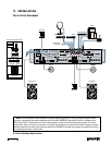
Connections
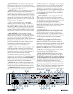
Connecting the Program Sources
All four Program Inputs use unbalanced RCA
connectors. They accept line-level signals (–10
dBV). Each of the Program Inputs is equipped with
an AGC circuit instead of input trim controls. These
circuits automatically adjust the gain for the best
signal-to-noise ratio according to the strength of the
input signal. It also ensures that the relative volume
level remains the same when switching between
input sources.
Use high-quality, two-conductor shielded cable
to make these connections.
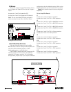
Connecting the Microphones
If using the XLR input for the paging microphone,
wire it per AES standard where pin 1 is ground
(shield), pin 2 is signal high (+), and pin 3 is signal
low (–). If using the Phoenix-type connector, strip
the wire back about 1/4" inch, insert the wire as far
as it will go into the appropriate hole in the
connector, and tighten down the screw with a small
slot-head screwdriver. It is recommended that you
use 20 or 22 gauge wire with the Phoenix-type
connectors, where pin 1 (the left-most pin) is
ground (shield), pin 2 is signal high (+), and pin 3 is
signal low (–).
The
MIC/LINE INPUT A and B
are for a local
microphone. This is a Phoenix-type connector, and
is wired as described in the previous paragraph for
the paging microphone.
All microphone inputs are equipped with a pad
switch for use with line-level signals. When connect-
ing a line-level signal to these inputs, make sure the
GAIN +40dB switches are in the up position.
Connecting the Speakers
The speaker output connectors are two-
conductor Phoenix-type, with a position-locking
mechanism. Use 16 or 18 gauge wire for
connecting the amplifier outputs to the speakers. If