


SP2400 – 13
The
REMOTE
connector is wired as follows:
Pin 1 = Ground (Shield)
Pin 2 = Data + (with +24V DC power)
Pin 3 = Data – (with +24V DC power)
Note: See the instructions with the remote
control for more information.
Connecting the RS485 Serial Port
This is a 3-pin Phoenix-type connector that
follows standard RS485 protocol. Select either a
data-grade shielded twisted pair cable or a standard
3-conductor microphone cable for this connection.
The
RS485
port is wired as follows:
Pin 1 = A (non-inverting I/O)
Pin 2 = G (Ground)
Pin 3 = B (inverting I/O)
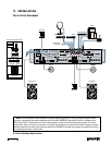
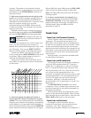
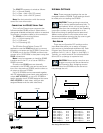
The SPLinker Sound Palette Control PC
application uses the
RS485
serial port to connect
between a computer and the SP2400. Connect the
PC RS485 port to the first SP2400, and then inter-
connect up to 16 SP2400s in the system using their
RS485
connections.
Note: It may be necessary to install an RS485
interface card in the PC, or to use an RS232 to
RS485 converter.
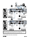
Since the two
RS485
ports are internally
connected in the SP2400, one can be used as an
input from the previous SP2400, and the other as
an output to the next SP2400.
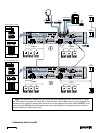
Up to 16 SP2400s can be connected together
with 32 independent zones (each zone assigned a
unique
AMP ADDRESS
), or up to 32 SP2400s in
stereo operation (each SP2400 assigned the same
AMP ADDRESS
on both sides, with one side
assigned Master and the other side Slave).
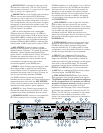
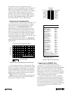
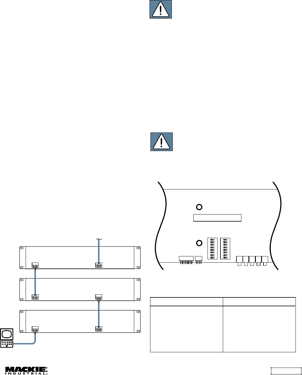
Bus Assign Switch Chart
Internal Settings
Note: There are several settings that can be
changed inside the SP2400. These settings should
be made prior to installing the SP2400.
CAUTION: These servicing instructions
are for use by qualified personnel only. To
avoid electric shock, do not perform any
servicing other than that contained in the Operating
Instructions unless you are qualified to do so.
Refer all servicing to qualified service personnel.
Make sure the power is off and the power cord
disconnected
before removing the top cover to gain
access to the inside of the SP2400.
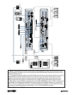
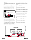
Bus Assign
There are two 8-position DIP switches on the
Input Board that allow you to assign a Program
Input source to the balanced expansion bus. Each
Program Input Source has four corresponding
switches: Left (+), Left (–), Right (+), and Right (–).
Typically, you would move all four switches either
down (off) or up (assign to expansion bus).
CAUTION: Never assign more than one
program source to the same channel on
the Expansion Bus. Assigning sources
from more than one SP2400 onto the same bus
may damage the unit.
S3 S4 J8 J9 J10 J11 J12
S1
S2
SP2400 INPUT BOARD
REAR PANEL
12345678
ON
12345678
ON
Signal Switch No.
Input 1 Left (+) S1-1
Input 1 Left (–) S1-2
Input 1 Right (+) S1-3
Input 1 Right (–) S1-4
Input 2 Left (+) S1-5
Input 2 Left (–) S1-6
Input 2 Right (+) S1-7
Input 2 Right (–) S1-8
Signal Switch No.
Input 3 Left (+) S2-1
Input 3 Left (–) S2-2
Input 3 Right (+) S2-3
Input 3 Right (–) S2-4
Input 4 Left (+) S2-5
Input 4 Left (–) S2-6
Input 4 Right (+) S2-7
Input 4 Right (–) S2-8
RS485
RS485
RS485
To Next SP2400
RS485
RS485
RS485
Laptop with
SPLinker PC Application