


SP2400 – 4
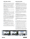
FRONT PANEL FEATURES
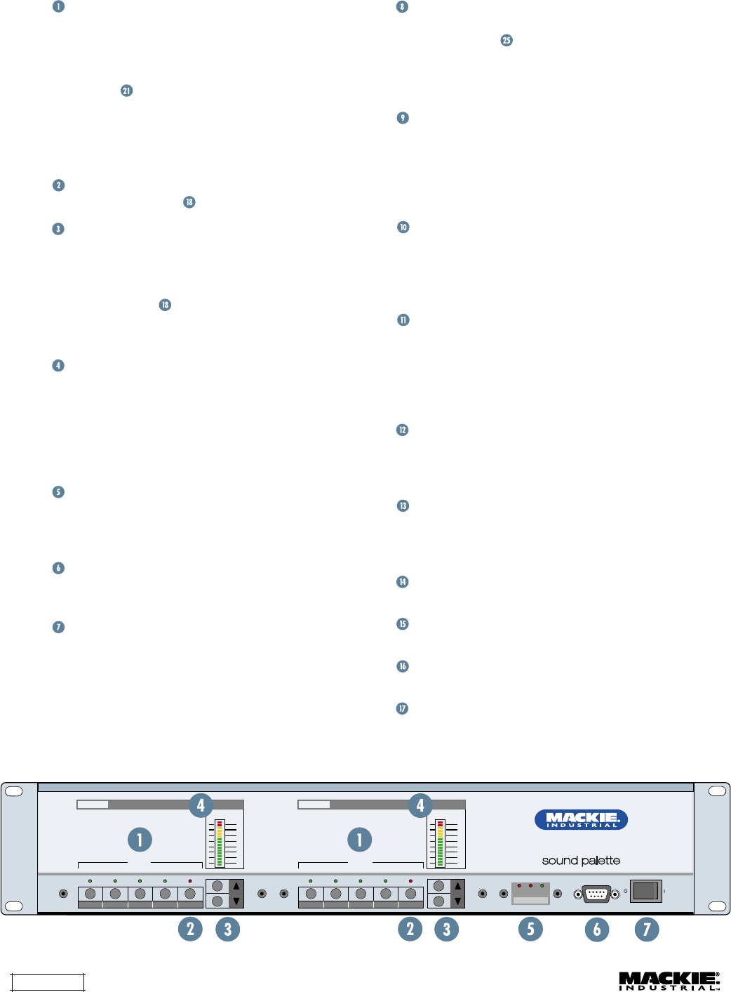
INPUTS
select buttons are used to choose the
program source for its respective zone. Only one
source may be selected at a time. These are non-
priority inputs. However, Input 4 can become a
Program Priority Input by setting the
AMP
ADDRESS
switch #7 UP. In this mode, when a
signal is present on Input 4, it automatically
overrides whatever input source is selected for that
zone. This is useful for jukeboxes or alternative
paging configurations.
INPUT OFF
deselects Inputs 1-4 and activates
the
MIC/LINE INPUT
.
MASTER VOLUME
is used to adjust the overall
volume level for Inputs 1-4.
When
OFF
is selected, the Up/Down
MASTER
VOLUME
buttons adjust the output level for the
MIC/LINE INPUT
. The Master Volume setting for
Inputs 1-4 is retained in memory, and is recalled
when a program source is selected.
The
Meter
indicates the level at the
PRE OUT
jack. Normally, it operates as a peak program meter
(PPM). When adjusting the
MASTER VOLUME
level, the meter changes from level indication to
level setting indication. After five seconds, the
meters switch back to normal peak program
metering.
There are three
STATUS
indicators. The
OVERLOAD
LEDs indicate when one of the
amplifiers is beginning to current limit. The
ON
LED indicates when the SP2400 is operating.
The
COMM PORT
is used to connect to the
optional DSP card with a Palm™ Handheld or PC-
compatible laptop computer for configuration.
Turning the
POWER
switch on activates the soft-
start circuit in the power supply. The soft-start
circuit impedes in-rush current from the AC supply.
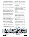
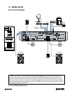
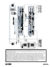
REAR PANEL FEATURES
PROGRAM INPUTS 1-4
are stereo RCA
unbalanced inputs that accept line-level signals. The
LOCAL/REMOTE
switches on the rear panel select
either the local program input signal connected here
or the program signal on the expansion bus. See
"Expansion In/Out" on page 18 for more information.
DIRECT OUTPUT
is a buffered line-level output
providing the stereo signal from the program source
connected to
INPUT 1
. Signal is always present at
the
DIRECT OUTPUT
, regardless of whether
INPUT 1
is selected as the source. This is useful for music-
on-hold and other external applications.
PAGING MIC
is the connection for the paging
microphone. There are two connectors available: a
3-pin XLR and a 3-pin Phoenix-type connector. In
both cases, pin 1 is ground, pin 2 is signal high (+),
and pin 3 is signal low (–).
CONTROL
is a Phoenix-type connector for
connecting external normally-open switches for
remote paging. Three options are available: page to
Zone A, page to Zone B, and page to the entire
system (
ALL CALL
). Connect the switches between
GROUND
and the option of choice.
PHANTOM
applies phantom power (+24VDC) to
pins 2 and 3 of the microphone input. Move both
switches to the down position to turn on phantom
power.
The
GAIN +40 dB
DIP switch is used to set the
gain for use with either a mic-level or a line-level
signal. Move both switches to the down position for
mic-level signals, and up for line-level signals.
The
GAIN
variable control is used to trim the mic
preamp gain for the best signal-to-noise ratio.
The
LOW
variable control is a shelving filter that
provides 12 dB of boost and cut below 100Hz.
The
HIGH
variable control is a shelving filter that
provides 12 dB of boost and cut above 12kHz.
The
PAGING MIC VOX
variable control adjusts
the ducking threshold for the paging mic. Rotate the
control clockwise to reduce the threshold. Rotate the
control counterclockwise to increase the threshold.
SP2400 MUSIC CONTROLLER
INPUTS INPUTS
OFF
3
0
3
6
9
15
30
55
OFF
3
0
3
6
9
15
30
55
A
B
ON
OVERLOAD
STATUS
POWER
COMM PORT
ZONE A
MASTER
VOLUME
ZONE B
MASTER
VOLUME
1234 1234