


SP2400 – 12
+15VDC (w/J3 INSTALLED)
–15VDC (w/J2 INSTALLED)
N/C
PAGING MIC (+)
INPUT 4 RIGHT (+)
INPUT 4 LEFT (+)
INPUT 3 RIGHT (–)
INPUT 3 LEFT (–)
GROUND
INPUT 2 RIGHT (+)
INPUT 2 LEFT (+)
INPUT 1 RIGHT (–)
INPUT 1 LEFT (–)
PAGING MIC CONTROL
PAGING MIC (–)
INPUT 4 RIGHT (–)
INPUT 4 LEFT (–)
GROUND
INPUT 3 RIGHT (+)
INPUT 3 LEFT (+)
INPUT 2 RIGHT (–)
INPUT 2 LEFT (–)
GROUND
INPUT 1 RIGHT (+)
INPUT 1 LEFT (+)
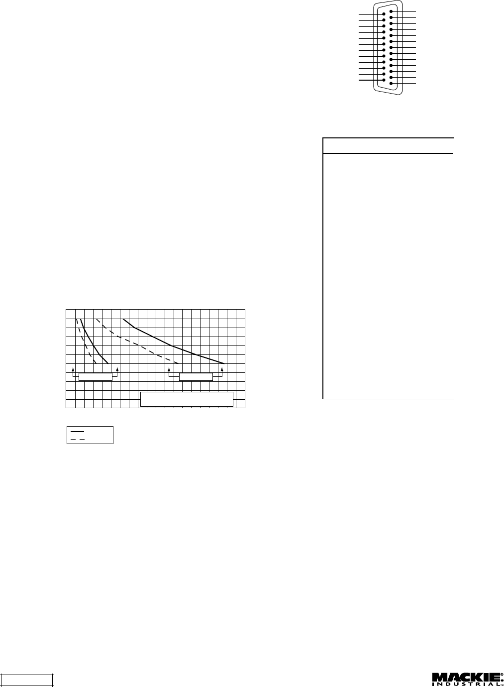
EXPANSION I/O
1
14
25
13
Signal Pin No.
Input 1 Left (+) Pin 1
Input 1 Left (–) Pin 14
Input 1 Right (+) Pin 2
Input 1 Right (–) Pin 15
Ground Pin 3
Input 2 Left (+) Pin 16
Input 2 Left (–) Pin 4
Input 2 Right (+) Pin 17
Input 2 Right (–) Pin 5
Ground Pin 18
Input 3 Left (+) Pin 6
Input 3 Left (–) Pin 19
Input 3 Right (+) Pin 7
Input 3 Right (–) Pin 20
Ground Pin 8
Input 4 Left (+) Pin 21
Input 4 Left (–) Pin 9
Input 4 Right (+) Pin 22
Input 4 Right (–) Pin 10
Paging Mic (+) Pin 23
Paging Mic (–) Pin 11
N/C Pin 24
Paging Mic Control Pin 12
–15VDC (w/J2 Installed)
Pin 25
+15VDC (w/J3 Installed)
Pin 13
Note: There is a 0.5 amp limit on
the ±15VDC supply.
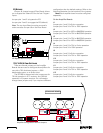
Connecting the REMOTE Bus
This is a 3-pin Phoenix-type connector
specifically for connecting the optional remote
control. Use a high-quality three-conductor shielded
cable to make this connection, such as Belden
8451, 9451, or equivalent. The lower the nominal
capacitance of the wire, the more distance you can
have between the remote control and the SP2400
before suffering transmission losses.
Strip the wire back about 1/4 inch, insert the
wire as far as it will go into the appropriate hole in
the supplied Phoenix-type connector, and tighten
down the screw with a small slot-head screwdriver.
It is recommended that you use 18 to 24 gauge
wire for the remote control connections, depending
on the distance between the SP2400 and the
remote control.
Expansion Bus Connection Chart
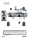
the amplifier output is configured for 8-ohm
operation, connect the speaker output directly to an
8-ohm load. The amplifier will deliver up to 250
watts to each speaker. If the amplifier is configured
for either 70V or 100V operation, connect the
speaker output directly to the distributed system.
No output transformer is required. Make sure that
the taps on the speakers add up to 200 watts or
less per amplifier for 70V or 100V systems.
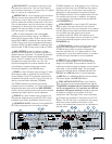
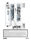
Connecting the Expansion Bus
These are 25-pin D-Sub connectors (DB25F). The
two connectors are wired in parallel, so it doesn’t
matter which one you use as an input or output.
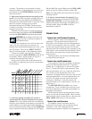
The signals on the
EXPANSION IN/OUT
are
balanced so they can be transmitted down long
lines. The limiting factor is the capacitance of the
cable, which causes the higher frequencies to roll-
off as the capacitance increases (see chart below).
The chart indicates the lengths of cable at which
the high-frequencies are 1 dB down and 3 dB, using
cable rated at 20pf/ft and 30pf/ft.
Use shielded twisted pairs for the
EXPANSION
cable to ensure the best rejection of external noise
(EMI and RFI).
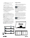
Maximum Feet of Cable vs. High-Frequency Roll-Off
Feet of Cable (24AWG)
0
0
100
200
300
400
500
600
700
800
900
1000
1100
1200
1300
1400
1500
1600
1700
1800
1900
2000
1.6K
3.15K
4K
5K
6.3K
8K
10K
12.5k
16K
20K
High-Frequency Rolloff
20pf/ft
30pf/ft
–1 dB point –3 dB point
Expansion Bus Output Impedance = 220Ω
Expansion Bus Input Impedance = 200KΩ
For local interconnection of the Expansion Bus,
the use of standard computer cable with an overall
shield is acceptable, such as Belkin Pro Series 25-
Conductor Straight-Through Cable Assembly (Part
Number F3D111-06) or equivalent. Ensure that the
cable is wired straight-through and terminated to
DB25M connectors on each end.
Note: The use of ribbon cable is permissible for
these connections, only where the total length of
each cable is 12" (30cm) or less.
Distance Chart for SP2400 Expansion Bus Cable