


AR13D RIDE-ON TANDEM DRUM ROLLER — OPERATION & PARTS MANUAL — REV. #2 (09/15/11) — PAGE 19
AR13D RIDE-ON ROLLER — ROLLER COMPONENTS
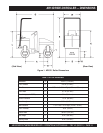
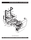
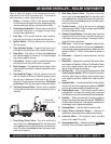
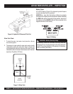
Figure 4 shows the location of the components and basic
components for the AR13D compaction roller. The function of
each component or control is described below:
1. Battery – Provides +12VDC to the electrical system,
and is located underneath foot plate. Replace only with
recommended type battery, see specification Table 1.
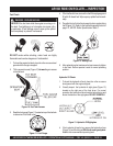
2. Articulating Locking Bar – Always make sure that the
articulating locking bar is engaged during lifting,
transport and maintenance.
3. Foot Step – To lift yourself onto the roller's platform,
place foot into foot step, then grab hold of hand rail.
4. Ignition Switch – With key inserted, turn clockwise to
start the engine.
5. Rear Sprinkler System – A gravity feed spray bar is
provided for the wetting the roll for asphalt pavement.
6. Rear Roller – This roller is a 30 inch wide
steel drum
with beveled edges (no vibration). The beveled edges
help prevent asphalt marring.
7. Lifting Point – Attach a crane or suitable lifting device
to this point when lifting of the roller is required.
8. Rear Scrapper – This adjustable rear scrapper blade
helps prevent the buildup of material between the drum
and frame.
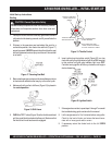
9. Fuel Tank/Fuel Gauge – The fuel capacity of the fuel
tank is 9.5 gallons (36 liters). Read the gauge on top of
the fuel cap to determine if fuel level is low. Fill with
diesel fuel. To gain access to the fuel tank,
tilt the front
seat forward
. Fuel tank has a spill containment feature
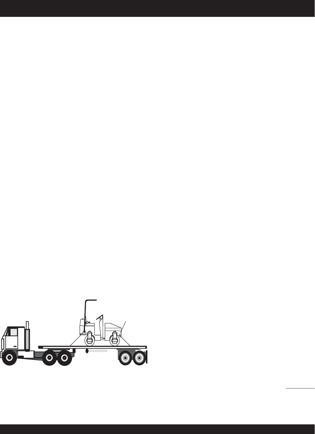
10. Tie-Down Transport Point – Attach a chain or suitable
tie-down device to this point when transporting of the is
required.
TRANSPORT
TIE-DOWN POINT
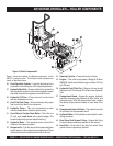
12. Rear Spray Control Valve – This valve controls the
flow of water to the
rear spray bar
.Turn the water valve
to the
open
position (counterclockwise) to let water flow,
return this valve to the closed position (clockwise) when
water is not required.
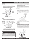
13. Throttle Control — Pull all the way out to achieved
maximum engine RPM's. To idle the engine, push the RED
stop button inwards all the way.
14. Vibration Control Button – Press this button to activate
the eccentric that will produce a vibration frequency of
4,400 vpm (vibrations per minute). Pressing the button
again will stop the vibrations.
15. Shift Lever — Push the lever
forward
to makethe roller
travel in a forward direction, pull the lever
backward
to
make the roller travel in a reverse direction. Maximum travel
speed is 4.8 MPH ( 7.7 KPH). Center position is neutral, no
travel.
16. Hour meter — Indicates the number hours the unit has
been in use.
17. Water Tank — Remove filler cap and fill with water. Water
tank capacity is 40 gallons (152 liters). To determine if water
level is low, visually inspect water level gauge (tube) at
rear of roller. Add water as necessary.
18. Roll-Over Bar — This unit may be equipped with a
Roll
Over
Protection System
(ROPS) to protect the operator
when the roller is used on slopes, open trenches, sharp
turns, slippery surfaces or objects in the rollers's path of
travel.
19. Operator's Seat —
A contoured seat that provides visibility
of both front rear drum edges during
operation.
NEVER!
start the roller unless seated in the operator's seat.
20. Parking Break Lever — Pull the lever upward to set the
parking break. To release the parking break, press and
hold the button on top of the lever and push lever downward.
21. Seat Belt — When using the roller in working conditions
always have the operator wear the seat belt.
NEVER
use
the roller without a seat belt. If the seat belt becomes worn
or damaged, have it replaced immediately.
22. Steering Wheel — Use this wheel to steer the roller.
23. Engine Status Indicator Gauge — Indicates oil
temperature, water temperature, glow plug and battery.
24. Hydraulic Motor – This hydraulic motor provides
control for the
rear
of the roller
25. Documentation Box — Maintain and store
at all times
Operation, Parts, and Engine manuals in this box.
11. Front Spray Control Valve – This valve controls the
flow of water to the
front spray bar
.Turn the water valve
to the
open
position (counterclockwise) to let water flow,
return this valve to the closed position (clockwise) when
water is not required.