


AR13D RIDE-ON TANDEM DRUM ROLLER — OPERATION & PARTS MANUAL — REV. #2 (09/15/11) — PAGE 29
AR13D RIDE-ON ROLLER — MAINTENANCE
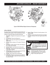
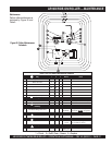
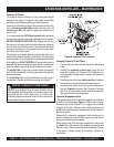
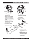
Drum Drive
The drum drive circuit is a
parallel
,
closed loop system
(Figures 29 and 30) consisting of a hydrostatic pump, two
relief valves, a freewheel engagement valve, front and rear
drum drive motors.
The hydrostatic pump is manually controlled by a cable
connected to the forward/reverse shift lever located on the right
side of the operator seat. When the shift lever is placed in forward,
high-pressure oil is supplied by the hydrostatic pump to the valve
block (
port A
). The valve block (manifold) directs this high-
pressure oil to the front and rear drum drive motors. Return oil
from the motors is returned to the valve block (
port B
) and is
returned to the suction side of the hydrostatic pump.
When shifted into reverse, the high-pressure and suction ports
on the hydrostatic pump are reversed. Oil flow is then in the
opposite direction of forward (
port B
becomes high-pressure
and
port A
becomes suction)
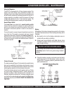
Vibration and Steering
The vibration and steering system is an
open loop circuit
operated by a gear type pump. Separate relief valves control
each circuit. This system consist of the gear pump, relief valves,
electric vibration control valve, vibration drive motor, steering
valve, and steering cylinder.
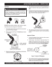
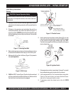
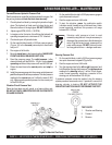
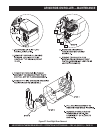
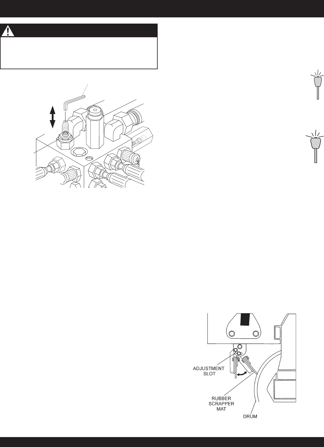
FREEWHEEL
ENGAGEMENT
VALVE
ALLEN
WRENCH
OPEN
CLOSED
Figure 27. Freewheel Engagement Valve
The freewheel engagement valve (towing) is only for
emergency use
. DO NOT move roller over 2 MPH or long
distances as hydraulic system component failure could result.
The vibration circuit is controlled by an electric control valve
located on the valve block (manifold). This valve is controlled by
the “
ON/OFF
” pushbutton switch mounted on top of the travel
lever.
High-pressure oil is supplied by the pump to the
valve block (
port P
) and is directed to the electric
control valve. When the pushbutton switch is in the
“
OFF
” position, this valve is
open
allowing oil to go
to the steering valve, without driving the vibration
motor.
When the switch is in the “
ON
” position, the
electric control valve
closes
and oil is directed
out of
port 1
to the vibration motor. Return oil
from the motor returns to the valve block via
port
2
and is directed to the steering valve.
Steering is controlled by a
steering valve
and
cylinder
(Figures
29 and 30). The steering wheel is direct coupled to the steering
valve controling the oil flow to the cylinder. Oil supplied from the
vibration circuit is directed to
port 3
which connects to
port P
of
the steering valve. When steering is not being used, oil passes
out of
port T
of the valve block and returns to the hydraulic tank.
When the steering wheel is operated, the steering valve closes
and oil is directed to ports L or R to extend or retract the steering
cylinder.
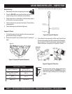
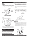
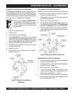
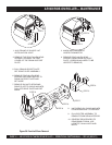
Rubber Scrapper Mat
Rubber scraper mats have been provided for the cleaning of the
front and rear drums. Adjust the scrapers mats as close as
possible to the drums, using the slotted holes (Figure 28)
provided. Replace these rubber mats when they become badly
worn.
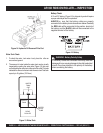
PUSH
TO
START
CLOSED
(ON)
PUSH
TO
START
CLOSED
(ON)
Figure 28. Scraper Bar Adjustment
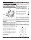
CAUTION - Freewheel Engagement Valve