Copyright© 2003 Pacific Digital Corporation Page 9
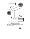
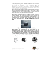
to the ends of this bar part B2. Slide this combination onto the vertical
bars Part B2. See illustration in Figure 5. Adjust the upper bar
combination to be almost to the top (about 4 to 5 inches down from top).
Slide the remaining Part D clamp on the left vertical bar Part B2. This
will be used later for your red Hi-Hat pad.
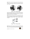
Step 5: Install a rubber cap part A2 to the top of each of the vertical bars
part B2. Tighten all bar-connection screws and be sure the rack is stable.
Tighten all screws for parts C clamps. Tighten all screws for Part D
clamps until they are snug, but can be moved and turned.
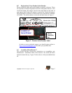
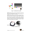
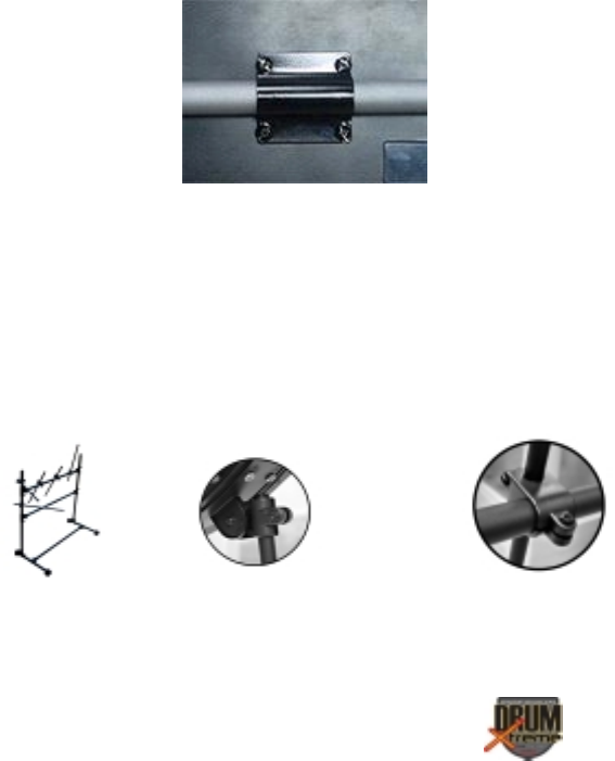
Step 6: Install the Master Controller (SV-BOX) by using the Part G
clamp to mount the Part SV-BOX to the lower (center) horizontal bar
Part B2 as shown below in Figure 6 using (4) Part H screws. The
multiple connection ports of the Master Controller should face up for
easy access. Adjust and tighten. Note: Do not tighten the screws too
hard.
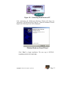
Figure 6 – Attaching the Master Controller
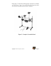
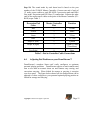
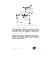
Step 7: Each of the Percussion Pads are color coded. Use the
illustrations in Figure 7 for pad assembly. Insert (10) Part A3 to each end
of (5) drum-arm rods Parts B3. Attach (5) Part E adjustable brackets to
each of the percussion pads (one part DX-8 and 4 part DX-5) using Part
F screws and nuts. The gear side of Part E adjustable bracket matches
with the gear side of the pads (Parts DX-8 & DX-5). Tighten finger tight
only at this point.


