


VX
PAGE 15
CENTURY SERIES
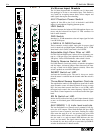
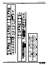
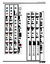
STEREO Switch w/LED
Like the AUX 1-6 controls, AUX 7&8 Individual Level
Controls normally send a summed (L+R) signal to the AUX
outputs. When the STEREO switch is depressed, AUX 7 and 8
become a send ‘left’ and ‘right’ send respectively. This can be
used for a stereo effects send.
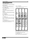
WIDTH Control / Balance
Dual concentric control pair. Outer control sets image width
for the outputs to L, R and Mono. The outputs to Group buses
are not affected by Image Width.
STR = normal stereo
MONO = summed L&R in both channels
REV = mirror image of normal
Inner control 'Balance' adjusts image position, extreme L and
extreme R setting attenuate the opposite sides about 20dB.
When LCR is selected, the Balance control changes function.
Fully clockwise = full level to center, no signal to L&R
Fully counter-clockwise = full level to L&R, none to center
50% rotation = equal levels to L, R & Center outputs.
SUM
combines L&R audio into a mono mix for the assigns to group
mixes only.
MUTE Switch w/LED
Mutes the channel and all send functions. Mute also responds
to the Mute Group system and to the VCA Group Mute if
selected (refer to User Options). The LED illuminates when
the channel is muted.
MONO Bus Assign Switch w/LED
Assigns audio to the Mono bus.
LCR Switch with Indicator
Controls the function of the L-R and M assign switches in
combination with the Balance control. When LCR is selected,
the Balance control provides continuous variation of outputs to
the L, R & Mono mixes.
Full clockwise = full level to mono, none to L-R.
Full counter-clockwise = full level to stereo, none to mono.
Refer also to Special facilities.
Bus Assign Switches,L-R & Mono
w/LEDs
Connect the post fader stereo audio to the output buses. These
outputs are always affected by the Width and Balance controls.
Balance provides L-C-R panning function to the three output
buses when the LCR switch is selected.
SOLO Switch w/LED
Operator monitor facility, switches channel audio into the
headphones and SOLO meters in stereo. Choice of PFL or
AFL. Unaffected by mutes.
L&R PEAK & SIG LEDs
Input level metering for the L and R channels. The green signal
LEDs turn on at about -30dB and brighten with increasing
level. They show the pre-amp output levels.
Red peak LEDs turn on 3dB before overload and show the lev-
els post-fader, pre-fader and at the preamp output.
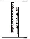
Fader
100mm VCA fader adjusts the channel stereo audio level.
Controls all outputs of the channel except those Aux output
sections selected pre-fader.
VCA Group 1-8 selectors
Assign the channel VCA to the VCA group control buses. Puts
the channel audio level under the (remote) control of the VCA
Group fader along with other channels assigned to the same
group. Independant of the Group Audio Assign section above.
VCA LED
Indicates VCA gain (i.e., gain of fader stage) via a two-color
LED. Indications are as follows: Green - intensity indicates
gain status (gain of fader stage). Red - indicates maximum
VCA gain has been reached, approximately 15dB. When the
gain LED is red then further requests for increased level, by
moving the channel fader or the VCA Group fader up, will
produce no response.
Mute Group selectors A-D
Assign input channels to any of the four Scene Mute groups.
Mute response occurs only when the group Master has been
activated.
Mute Groups Safe Switch w/LED
Bypasses the selected Scene Mute assignments. No Scene
Mutes can occur. An associated green LED indicates the chan-
nel is in a SAFE (isolated) state.