


VX
APPENDIX A
CENTURY SERIES
General Specifications -
Vx Console
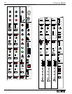
Technical specifications for the Century Vx console.
Available (Eight Bus) Configurations
20 inputs (32 Frame) 32 inputs (44 Frame)
40 inputs (52 Frame) 52 inputs (64 Frame)
All Century Vx consoles are available with stereo input modules.
Frequency Response
+0.0, -0.5dB, 20Hz to 20 kHz (referenced to 1kHz)
Total Harmonic Distortion
Mic input to Group output
20Hz to 20 kHz at +15dBu <0.02%
Phase Response
20Hz to 20 kHz +30°, -20°
Noise (22Hz to 22kHz)
Mic EIN -129 dBu
Mix bus Output Noise (20 ch routed) - 80 dBu
Aux bus Output Noise (20 ch routed) - 80 dBu
Crosstalk (Measured at 1kHz)
Channel Mute >102 dB
Channel Fader Attenuation > 96 dB
Channel Routing > 85 dB
Channel Aux Send Attenuation > 93 dB
Input/Output Impedances
Mic Input 4kΩ balanced
Line Input >10kΩ balanced
Outputs 140Ω balanced
Input/Output Levels (0VU = +4 dBu, 1.23V RMS)
Mic Input Sensitivity + 4 to -62 dBu
Line Input Sensitivity + 12 to -38 dBu
Input Insertion Point Level + 4 dBu
Output Insertion Point Level - 2 dBu
Nominal Output Level + 4 dBu
Maximum Balanced Output Level +28 dBu
Net Weights
32 Frame 146 lbs. / 66.3 kg
44 Frame 197 lbs. / 89.5 kg
52 Frame 239 lbs. / 108.5 kg
64 Frame 293 lbs. / 133.0 kg
Architect’s & Engineer‘s
Specifications - Vx Console
The following text should be used when specifying a Century
Vx in a bid or proposal.
The Vx live sound console shall be constructed in a modular fashion and be
housed in a steel frame of (32, 44, 52, or 64) module positions. Vx Consoles
shall include an 8 channel VCA level control system as well as an 8 channel
audio subgroup system. The console shall utilize XLR-type lighting device
connectors with dimmer system. A meter bridge using mechanical meters with
solid state illumination shall be included. Signals to be monitored include
Left, Right, Mono (Center), Stereo Solo and 8 Group output signals. On 52
and 64 module position frames, 8 Auxiliary output meters are also provided.
The Vx live sound console shall feature a defeatable Left-Center-Right (LCR)
panning system on input and group modules. • On each input channel: all
microphone inputs shall be electronically balanced and accessed via XLR con-
nectors and have an EIN of -129 dBm. All input channel line inputs shall be
electronically balanced and accessed via 1/4" TRS jacks. Input module insert
and return points shall be via individual 1/4" jacks and controlled by a front
panel switch with LED. Additional input controls include: a +48 volt Phantom
Power switch, a -15 dB Pad switch (-20 dB for stereo input channels),
adjustable High Pass Filter control (20-400Hz) with on switch and LED, a
Polarity Reverse switch with LED, and 4-band sweep EQ (LF- 40-800Hz,
LMF- 100Hz-2kHz, HMF- 400Hz-8kHz, HF- 1.5k-20kHz) with Peak/Shelve
switches on the high and low EQ bands, switchable bandwidth on low-mid
and high-mid bands, and an EQ In switch with LED. Each input channel shall
also have a FET-controlled Mute switch with LED, affecting all assigned out-
puts including Auxiliary sends. The mute system may be defeated to the auxil-
iary sends by use of an internal jumper system. Assignment switching is pro-
vided to the following output sections: Left/Right, Mono, Subgroup 1, 2, 3, 4,
5, 6, 7 and Subgroup 8. An LCR switch shall reconfigure the Left/Right and
Mono assignment system to a true Left-Center-Right mix system. A Pan On
switch will allow conventional panning between any odd and even subgroup
assignment regardless of the position of the LCR configuration switch. A 5-
segment Signal level LED indicator will be provided on Mono input modules,
including a multiple sample point peak LED to monitor signal levels. Input
modules will also include a Solo switch with LED indicator, 8 VCA group
assignment switches, 4 Scene Mute preset switches, Scene Mute Safe switch
with LED, and a 100mm fader. Each input channel shall have eight Auxiliary
send level controls. Each Aux Send shall have the ability to be turned on and
off by pressing its associated send knob. A bi-color LED will indicate the sta-
tus of the send: Green=Aux switched on, Red=Aux switched on but send
muted, LED Off=Aux switched off. Signal source of each Aux mix bus is nor-
mally post channel fader but may be globally changed to a pre fader source
from eight individual switches within the master section. Individual channels
may be removed from the global pre/post fader signal source as well as Aux
Mute control by a series of internal jumpers on each input module. • The 8
VCA group assignment switches will allow each channel to be controlled by
any or all of the VCA group faders. A VCA bi-color LED will show VCA
control voltage with increasing green intensity, and will turn red when VCA
control limiting is reached. The Aux sends shall be globally switchable pre or
post fader with internal jumpers to select pre or post EQ and pre or post mute.
There shall be an Aux 8 Direct switch that allows the Aux 8 send knob direct-
ly to control the output of the 1/4" direct output connector. There will also be
an Aux 8 Pre switch which allows Aux 8 to be switched pre fader indepen-
dently of the global switch. Optional Stereo input modules with similar fea-
tures will be available. • Each Group module shall have VCA Group and
Audio Group mixing sections, and a Matrix section. The VCA Group section
shall have a Mute switch and Unity LED indicator. • The Audio group mix
section of the module shall have a Pan control, a Mute switch with LED,
Matrix meter switch, assignment switches for Left/Right and Mono with an
LCR configuration switch, a Fader Reverse switch with LED that allows the
group fader to control the level of the matrix output, a Solo switch, dynamic
signal present LED and peak LED, and a 100mm fader. Each Audio Group
mix section will have group insert connections. • The Matrix section shall
have controls for Group to Matrix Levels (G1-G8), L/R level to Matrix, Mono
and External level to Matrix, Talkback to Matrix (w/LED), Peak/Signal level
LED. The Matrix section shall also have a Stereo Program switch (w/LED) to
switch the L/R signal source to the Stereo Program input, a Solo switch, and a
master Matrix Out level control. • The master section shall have the following
features: eight Aux master controls with associated Global Pre, Solo and Mute
switches, a 100mm fader for each of the Left, Right, and Mono (Center) mas-
ter outputs with insert connections, an assignable Talkback system, Monitor
control system (with balanced XLR output), Stereo Program input section
with EQ, and a Scene Mute Master switch section, each with LED. • The
power supply shall be housed in a 14 gauge steel chassis and provide ±20V,
+24V, and +48V to the console. The power supply shall have the ability to be
daisy-chained to additional power supplies to provide a redundant operating
environment. Connection of two or more power supplies shall not require
additional hardware other than an interface cable. The live sound console shall
be: the Crest Audio Century Vx.
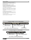
All Century Vx Consoles are available with optional stereo input
modules.
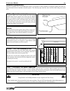
Eight Subgroup - 20, 32, 40, or 52 inputs
Configurations
Century Vx Consoles are available in
the following configurations: