


MASTER VOLUME (21)
Controls the overall volume level of the system. Once a desired balance of the clean and lead channel volume levels is
achieved, the entire system level may be increased or decreased with the Master Level Control.
STANDBY SWITCH (22)
Allows amp to be placed in standby or active mode. In standby mode the tubes remain hot, but the amplifier is not
operational. Eliminates warm up time, allowing the tubes to remain hot and ready for instantaneous operation.
ACTIVE LED (23)
The active LED indicator light will illuminate when the amp is in the operational mode. The standby switch (22) should
be switched to the active mode in order for the amp to be operational.
POWER SWITCH (24)
Supplies power to the unit. Depressed to the “ON” position, the power LED indicator (25) will illuminate indicating
power is being supplied to the unit.
POWER LED/ON (25)
Illuminates when AC Power is being supplied to the amp when the power switch (24) is depressed to the “ON” posi-
tion.
0
0
5
PRFAMP
SPEAKER OUTPUTS
-f
1
GND
0
8
LEVEL
SEND RETURN
120
“AC
12OW
RMSI44”
RMS
40 MIN
bO
HZ
rUSC
REMOTE SWITCH
-wx
-
SPEAKER JACKS PARALLELED
400
WATTS
5A
-1
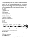
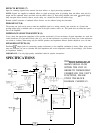
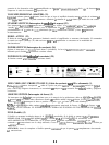
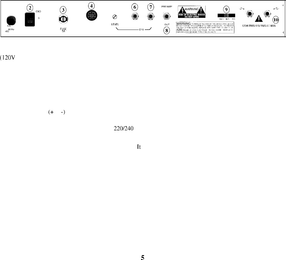
LINE CORD (1)
(12OV
units only) For your safety, we have incorporated a three-wire line (mains) cable with proper grounding facili-
ties. It is not advisable to remove the ground pin under any circumstances. If it is necessary to use the amp without
proper grounding facilities, suitable grounding adaptors should be used. Greatly reduced shock hazard exists when the
unit is operated with the proper grounded receptacles.
GROUND SWITCH (2)
Three position, rocker-type switch which, for most applications, should be operated in the center (zero) position. If hum
or noise is noticed coming from the speaker with the ground switch in the center position, place the ground switch to
positive or negative
(+
or
-)
to minimize hum. Should a hum/noise problem continue, consult your authorized Peavey
dealer, the Peavey factory, or a qualified service technician.
NOTE: The ground switch is not functional on 220/240 volt models.
FUSE (3)
A 5 amp fuse is located within the cap of the fuse holder.
Tt
must be replaced with the same type and value in order to
avoid damage to the equipment and to prevent voiding the warranty. If the amp repeatedly blows fuses, it should be
taken to a qualified service center for repair. WARNING: The fuse should only be replaced when the power cord has
been disconnected from its power source.
REMOTE FOOTSWITCH JACK (4)
Provided for the connection of the supplied remote footswitch. Footswitch is used to select the channel from clean to
lead and to select the effect, reverb, and tremolo on or off.
LEVEL (5)
Adjusts the voltage level of the effects loop. If the send level is too low for a particular effects device, turn the control
clockwise; if too high, counterclockwise.
EFFECTS SEND (6)
Output for supplying signals to external effects or signal processing equipment.
5