


EFFECTS RETURN (7)
Input for returning signals from external low-level effects or signal processing equipment.
NOTE: Signals are supplied to outboard effects or signal processing units by patching from the effects send jack (6)
output into the outboard unit(s) and back into the effects return (7) input using shielded cable with l/4” phone plugs.
Only non-gain effects devices (chorus, reverb, delay, etc.) should be used in the effects loop.
Remote (on/off) selection of outboard effects devices can be achieved using the footswitch.
PREAMP OUT (8)
The preamp out jack can be used to route the amplified signal to a mixing console, tape recorder, etc. Connect the
preamp output using a shielded cable to an input of the tape recorder, mixer, etc. This patch does not affect the opera-
tion of the amplifier.
IMPEDANCE SELECTOR SWITCH (9)
Use to select the appropriate impedance of the speaker enclosure(s). If two enclosures of equal impedance are used, the
switch should be set at one-half of that value (e.g., two 16 ohm enclosures: set switch to 8 ohms; two 8 ohm enclosures:
set switch to 4 ohms). When using only the internal speakers, the Impedance Selector Switch should be set to 16 ohm.
SPEAKER OUTPUTS (10)
Paralleled l/4” output jacks for connecting speaker enclosure(s) to the amplifier (minimum 4 ohms). When using more
than one enclosure, be sure to calculate the total impedance and set the impedance switch (9) accordingly. (See section
on Impedance Switch.)
IMPORTANT: Use only high quality, unshielded cable for speaker connections.
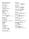
SPECIFICATIONS
PRE
POST
L
HIGH
INPUTS
PUSH
GAIN
PREAMP
L
SWITCH
f
BOOST
LOGIC /T
LOW
-
GAIN
RESONANCE PRESENCE
MASTER
LEVEL
PREAMP
OUT
-
P
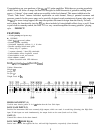
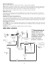
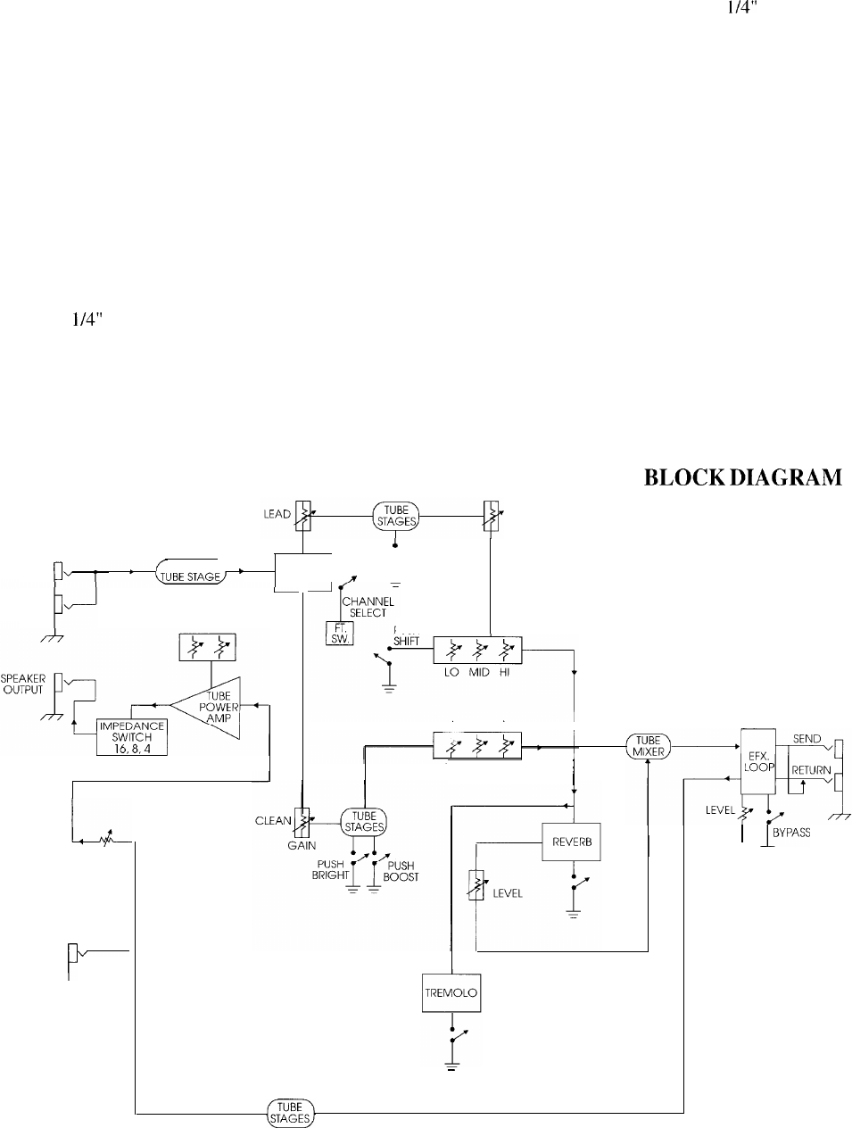
THIS
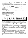
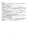
BLOCK DIAGRAM
SHOWS SIGNAL FLOW
WITHIN THE UNIT. IN
ORDER TO THOROUGHLY
UNDERSTAND THE UNIT’S
PUSH
LEAD EQ
FUNCTIONS, PLEASE
STUDY THE BLOCK
DIAGRAM CAREFULLY.
CLEAN EQ
LO MID HI
I
-
6
1
I”‘““”