


11
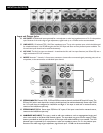
33
34
35
they be at 0 when channel gains are set; however, they can be used to
lower the overall sound level if needed.
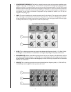
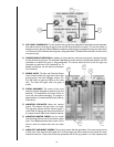
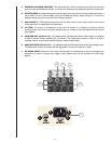
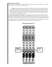
32. CONFIGURATION: The main outputs can be configured as full
stereo or as a mono sum of the left and right signals. When in dual-
mono mode, the left and right outputs become individual outputs with
their levels set independently by their master faders.
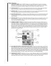
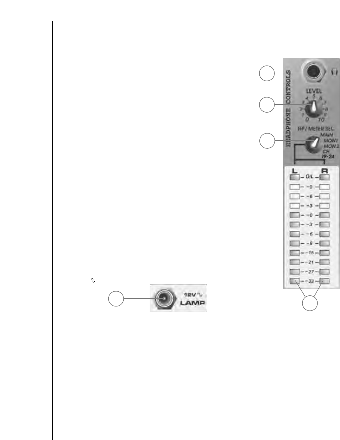
33. HEADPHONE OUTPUT: This stereo jack (TRS) provides drive for
the headphones. The level is set by the headphone level control.
Tip = Left, Ring = Right, Shield = Ground.
34. HEADPHONE LEVEL: This control sets the volume of the
headphones.
35. HEADPHONE/METER SOURCE: Selects the signal(s) sent to the
headphone amplifier and to the output meter array. Options include
the main L/R outputs, monitor 1, monitor 2 or a cue mix of channel
19/20, 21/22 and 23/24 pre-fader signals. This last position is useful for
setting up tapes and CDs (on channels 19-24). Muting the stereo
channels during cueing does not affect the headphone signal but
prevents the audio from being sent to the speaker systems.
36. LED METER ARRAY: A 12-segment LED array monitors the level of
the signals selected by the Headphone Source switch. When the switch
is in the MAIN position, the meters monitor the left and right outputs.
The 0 dB reference level corresponds to +4 dBu. In normal operation,
the channel gains should be set so that the meters light near 0 dB at
loud points in the service. The output trim attenuator on the rear panel
should then be adjusted for the desired house volume. This will give
the best signal-to-noise ratio. The same procedure should be used on
the monitor outputs, but the power amplifier input controls will need
to be set for desired volume. Setting the output trim is part of the S-
24 setup procedure.
37. 12V : This output is designed to power mixer lamps such as the
Peavey ML-1.
36
37