


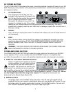
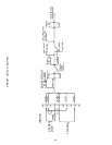
AC POWER SECTION
The AC POWER SECTION explains the proper connections/method to supply AC power to your XR
800F. Please pay close attention to the precaution(s) noted below in order to ensure both personal
and equipment safety.
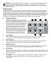
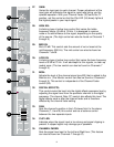
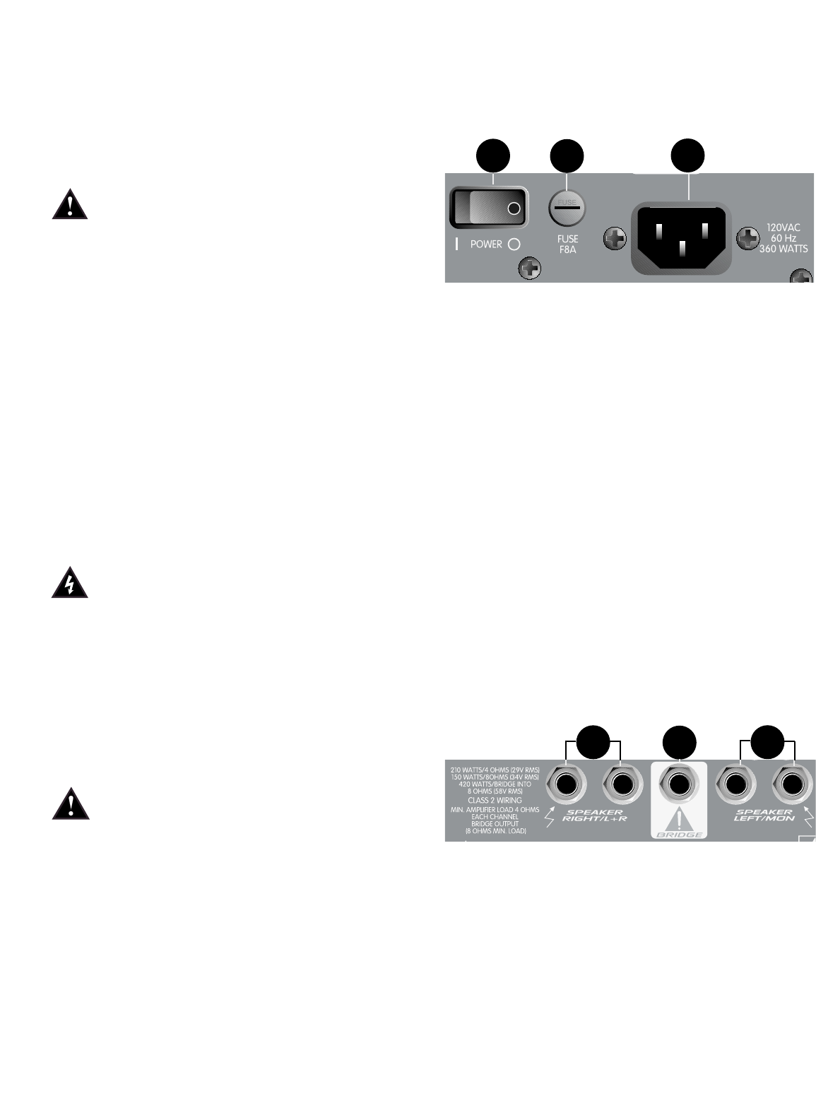
1. A/C POWER INLET:
This receptacle is for the IEC line cord
(included), which provides AC power to the
unit. Connect the line cord to this connector
and to a properly grounded AC supply.
Damage to the equipment may occur if an
improper line voltage is used. (See voltage
marking on unit.) Never remove or cut the ground pin of the line cord plug. This unit is
supplied with a properly rated line cord. When lost or damaged, replace this cord with one of
the proper ratings.
2. POWER:
This is the mixer’s main power switch. The Power LED indicator (21) will illuminate when the
unit is powered.
3. FUSE:
This is the main safety fuse for the AC line voltage. Only replace the fuse with one of the
exact same type and rating. IF THE FUSE CONTINUES TO OPEN, DO NOT REPLACE
WITH A LARGER FUSE. TAKE THE UNIT TO AN AUTHORIZED PEAVEY SERVICE
CENTER!
WARNING: THE FUSE SHOULD ONLY BE REPLACED WHEN THE POWER CORD HAS
BEEN DISCONNECTED FROM ITS POWER SOURCE.
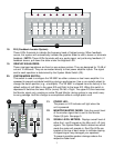
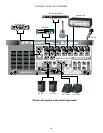
POWER AMPLIFIER SECTION
The POWER AMPLIFIER SECTION will explain the proper method of connecting your XR 800F
to your speakers. This is a very versatile area of the XR 800F. However, it is important that
you follow the precautions to insure safe operating impedances and avoid improper connections.
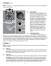
4. PARALLEL LEFT/RIGHT SPEAKER OUTPUTS:
These 1/4" jacks are the outputs for the two
internal amplifiers. You will notice that there
are two pairs of jacks with another jack in
the middle. The two pairs are the two (L/R)
amp outputs. Two cabinets can be connected to
each amplifier, as long as the combined impedance of the cabinets is not less than 4 ohms. (i.e.,
two 8 ohms cabinets in parallel = 4 ohms, four 16 ohms speakers in parallel = 4 ohms, etc.) Do not
use the Bridge Output (5) while using these outputs. The outputs from these jacks are
determined by the System Mode Switch (20).
5. BRIDGE OUTPUT:
The bridge output of the XR 800F allows the power of the left and right amplifiers to be
combined into one mono output in applications where only one speaker will be used. To use
the bridge output, the system mode switch must be in the Left/Right position. Connect an 8
ohm minimum impedance speaker to the center bridge output jack.
2
3
1
4
5
4
4