


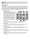
24. MASTER L/R FADERS:
This is the master level control for the L and R signals sent to the Left and Right Output
jacks. When in Main/Monitor mode [see System Mode Switch (20)] the Monitor Fader controls
the monitor signal present at the Left/Mon Power Amp Output (4). The Left and Right Faders
would then control the L/R Mix present at the Right/L+R Power Amp Output (4). The nominal
position for this control is the 0 dB position.
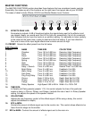
CHANNEL FUNCTIONS
The CHANNEL FUNCTIONS section describes the controls and input connections for each channel
of the XR 800F. Most features are found on all channels, however, there are some differences in
channel’s 7, 8 and 9. Therefore, this section is divided to properly indicate those differences.
CHANNELS 1-6
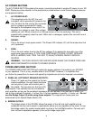
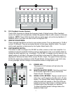
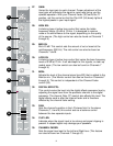
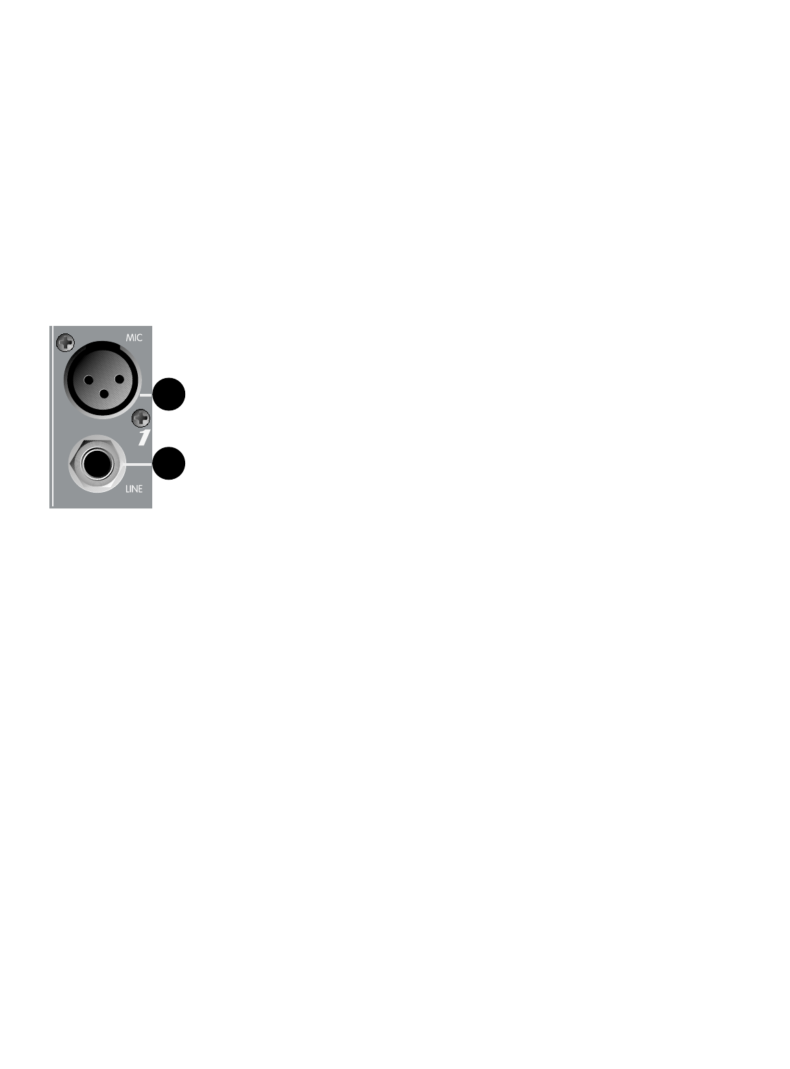
25. MIC INPUT:
XLR balanced, low impedance channel input optimized for a microphone
or other low-level source. Pin 2 is the positive input. Because of the wide
range of gain adjustment, signal levels as high as +10 dBV (2.45 V RMS)
can be accommodated. When the phantom power is enabled, this
connector has +48 V on Pins 2 (in phase) and 3 with Pin 1 as the ground
reference.
26. LINE INPUT:
1/4" balanced TRS line level input. The tip is the positive (in phase) input,
which can also be used for unbalanced inputs. This signal is connected
through a 20 dB pad to the mic input below it. Within the same channel, the Mic Input and the
Line Input cannot be used simultaneously. Channels 7 and 8 feature stereo versions of the
Line Input. (See features 36 and 37 page 10.)
25
26
8