


Philips Semiconductors Product specification
SA70161.3GHz low voltage fractional-N synthesizer
1999 Nov 04
10
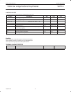
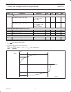
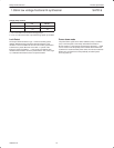
Charge pump currents
CP0
I
PHP
I
PHP–SU
0 3xI
SET
15xl
SET
1 1xl
SET
5xl
SET
NOTES:
1. I
SET
=V
SET
/R
SET
: bias current for charge pumps.
2. I
PHP–SU
is the total current at pin PHP during speed up condition.
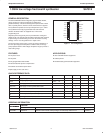
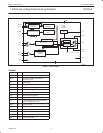
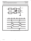
Lock Detect
The output LOCK maintains a logic ‘1’ when the auxiliary phase
detector ANDed with the main phase detector indicates a lock
condition. The lock condition for the main and auxiliary synthesizers
is defined as a phase difference of less than "1 period of the
frequency at the input REFin+, –. One counter can fulfill the lock
condition when the other counter is powered down. Out of lock (logic
‘0’) is indicated when both counters are powered down.
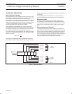
Power-down mode
The power-down signal can be either hardware (PON) or software
(PD). The PON signal is exclusively ORed with the PD bits in
B-word. If PON = 0, then the part is powered up when PD = 1. PON
can be used to invert the polarity of the software bit PD. When the
synthesizer is reactivated after power-down, the main and reference
dividers are synchronized to avoid possibility of random phase
errors on power-up.